
Automatic discharging machine

A technology of automatic blanking and transmission mechanism, which is applied in metal processing and other directions, can solve the problems of uneven incision, defective products, and low work efficiency, and achieve the effect of smooth and complete incision, consistent moment of inertia, and high cutting efficiency

Active Publication Date: 2017-04-26
山东华刃机械制造有限公司
View PDF9 Cites 2 Cited by
  • Summary
  • Abstract
  • Description
  • Claims
  • Application Information

AI Technical Summary

Problems solved by technology

[0004] In the production process of PVC mats such as brushed mats and brushed mats, the blanking of PVC mats is an indispensable process. The existing method of blanking mats is to manufacture stampers according to the outer dimensions of the products. The foot pads are transported to the workbench and placed, and then pressed down by the upper die. After pressing, the worker cuts with a knife according to the outer size of the die, which is prone to large errors and defective products; during the cutting process, Brushed mats and brushed mats are not easy to cut, the incision is not easy to be smooth and smooth, the labor intensity is high, the work efficiency is low, and it is not suitable for mass production
[0005] After retrieval, the application number is 2014105150575, a multifunctional automatic leather cutting machine, wherein the shearing device is mainly composed of a support plate, a rotating shaft, a knife, a knife holder, a shear plate and a motor, and there are Motor, the upper part of the motor is provided with a rotating shaft, and the two are connected by a coupling device; the rotating shaft is provided with a bearing and an eccentric bearing, the bearing is fixed on the support plate through a horizontal plate, and the eccentric bearing is connected to the connecting rod, and the connecting rod passes through The pins are fixed on the lower tool holder; there are guide rails at both ends of the tool holder, and the tool holder is connected to the tool. The eccentric bearing, the connecting rod, the tool holder, the tool and the guide rail form a crank-link mechanism. The mechanism works; however, due to the motors installed on the outside of the support plates on both sides, the rotational torques of the eccentric wheels at different positions on the same transmission shaft are different, that is, the end of the transmission shaft far away from the motor, due to the rotation of the motor, the end of the transmission shaft away from the motor will swing. As the distance away from the motor increases, the greater the swing of the transmission shaft, the greater the moment of inertia, which leads to different timing of the force point of the crank-link mechanism falling. The incision of the leather pad is uneven, or one end of the leather pad is not cut off, and there is adhesion; if the cutting amount is adjusted, long-term use will cause serious wear of the tool close to the motor, and a blunt knife will appear. After the blunt knife, the incision width of the leather pad will be inconsistent. , the incision is not smooth, affecting the appearance

Method used


Image

  • Automatic discharging machine
  • Automatic discharging machine
  • Automatic discharging machine

Examples


Embodiment Construction

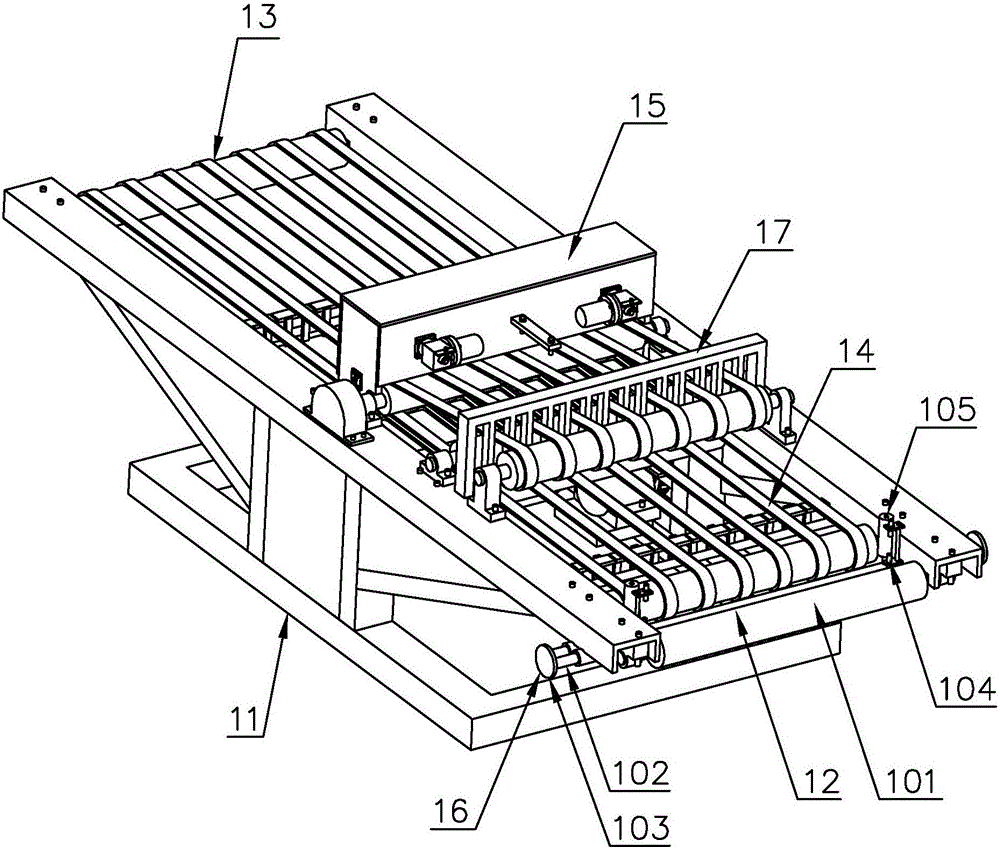
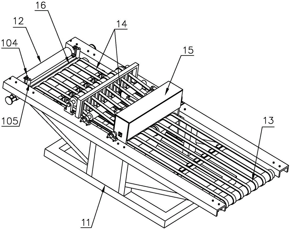
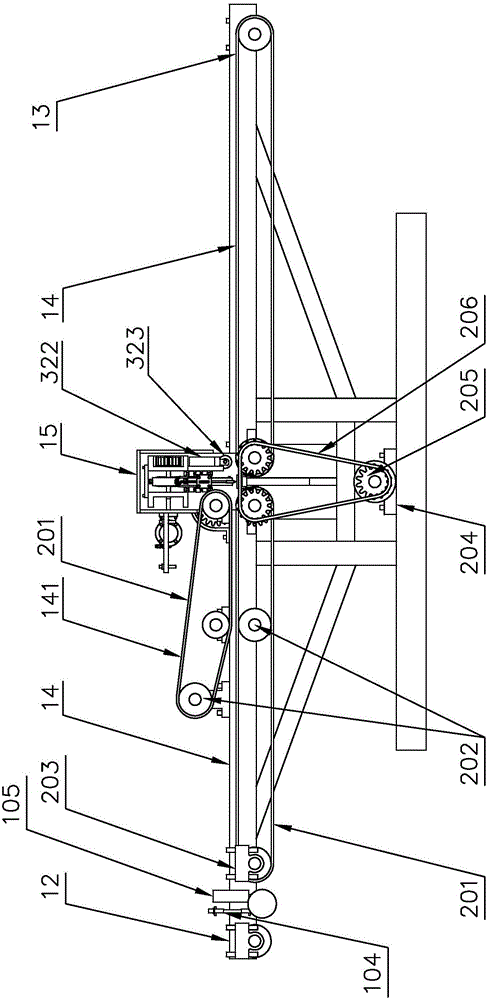
[0035] For the convenience of those skilled in the art to understand, the following in conjunction with the attached Figure 1-8 , to further specifically describe the technical solution of the present invention.

[0036] An automatic blanking machine, comprising a frame 11, a feed port 12, a discharge port 13, a transmission mechanism 14, a skin clamping mechanism 141, and a skin cutting mechanism 15, one end of the frame 11 is provided with a feed port 12, and the machine Frame 11 other end is provided with discharge port 13, and frame 11 is provided with transmission mechanism 14, and transmission mechanism 14 is movably linked on the frame 11 by bearing 203, and transmission mechanism 14 top is provided with clamping mechanism 141, and clamping mechanism 141 One side is provided with slicing mechanism 15, and frame is used for bearing transmission mechanism 14, skin clamping mechanism 141, peeling mechanism 15.

[0037] The transmission mechanism 14 comprises a feed end t...


PUM


Abstract

The invention discloses an automatic discharging machine. The automatic discharging machine comprises a rack, a feeding port, a discharging port, a transmission mechanism, a leather-clamping mechanism and a leather-cutting mechanism. The feeding port is formed in one end of the rack, and the discharging port is formed in the other end of the rack. The transmission mechanism is arranged on the rack, the leather-clamping mechanism is arranged on upper portion of the transmission mechanism, and the leather-cutting mechanism is arranged on one side of the leather-clamping mechanism. The leather-cutting mechanism comprises a fixing plate, a supporting plate, supporting frames, a knife plate, a cutting blade, a cutting plate, a cutting plate fixing plate, eccentric wheels, eccentric wheel supports, hinge pins and transmission shafts. A gear is arranged at the shaft end of each transmission shaft, every two adjacent transmission shafts are engaged with each other through the corresponding gear, and the transmission shafts penetrate through the eccentric wheels. The eccentric wheel supports are arranged on the outer sides of the eccentric wheels and fixedly connected to the knife plate through the hinge pins, and the cutting blade is arranged on the lower portion of the knife plate. According to the automatic discharging machine, leather cushions are synchronously cut off, and meanwhile the leather cushions are effectively trimmed; and cuts are smooth and complete, cutting-off efficiency is high, and labor intensity of workers is lowered.

Description

technical field [0001] The invention relates to the technical field of leather pad processing, in particular to an automatic blanking machine. Background technique [0002] At present, floor mats are mainly used in many high-end places such as hotels, guesthouses, restaurants, office buildings, etc. The maintenance and protection of soft ground is particularly important. If the main function of carpets is decoration, then the function of floor mats is even more important. In fact, in addition to having the same decorative function as carpets, floor mats take on tasks such as dust removal, water absorption, mud removal, and anti-slip from the moment they enter the door. In some special occasions, they also play the role of anti-fatigue and anti-static. [0003] Floor mats are divided into household mats, business mats, car mats, etc. according to their actual use occasions. The environmentally friendly floor mats and mats that are easy to wash and dry, environmentally friendl...

Claims


Application Information

Patent Timeline
Patent Type & Authority Applications(China)
IPC IPC(8): B26D9/00B26D1/08B26D1/14B26D5/16B26D7/26B26D7/20B26D7/28
CPCB26D1/08B26D1/14B26D5/086B26D5/16B26D7/20B26D7/2628B26D7/28B26D9/00
Inventor 孟凡涛孟凡东
Owner 山东华刃机械制造有限公司
Learn More