Automatic steel tube punching machine

A punching machine, punching mechanism technology, applied in metal processing equipment, feeding devices, manufacturing tools, etc., can solve the problem of gaps at both ends of the steel pipe, and achieve the effect of easy assembly and transportation

Active Publication Date: 2017-04-26
CHONGQING YOUBO MACHINERY MFG
View PDF9 Cites 3 Cited by
  • Summary
  • Abstract
  • Description
  • Claims
  • Application Information

AI Technical Summary

Problems solved by technology

[0004] The present invention intends to provide an automatic punching machine for steel pipes to solve the problem in the prior art that gaps tend to appear at both ends of the steel pipes after being punched because the steel pipes are obliquely fed into the die.

Method used


Image

  • Automatic steel tube punching machine

Examples


Embodiment Construction

[0015] The present invention will be described in further detail below by means of specific embodiments:

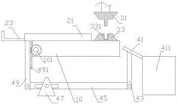
[0016] The reference numerals in the accompanying drawings of the description include: workbench 10, gear 101, guide plate 21, pusher plate 23, upper die 31, lower die 33, waste material collection box 331, support plate 41, first connecting rod 43, connecting rod Rod 45 , base 47 , second connecting rod 49 , collection box 411 , rack 491 .

[0017] Such as figure 1 The steel pipe automatic stamping machine shown includes a workbench 10, a guide plate 21 and a stamping mechanism that are all located above the workbench 10; The material plate 23; the stamping mechanism includes a reciprocating upper die 31 and a lower die 33 fixed on the workbench 10, the two ends of the upper die 31 and the lower die 33 are sloped, and the lower plane of the upper die 31 is provided with a punch , the upper plane of the lower die 33 is provided with a groove that matches the punch; a wa...


PUM


Abstract

The invention relates to the field of die processing, in particular to an automatic steel tube punching machine. The automatic steel tube punching machine comprises a worktable, as well as a guiding plate and a punching mechanism which are both positioned above the worktable, wherein the punching mechanism comprises an upper punch die doing reciprocating motion and a lower punch die fixed on the worktable; a lifting mechanism is further arranged below the worktable and comprises an inclined support plate, a first connecting rod, a link, a base and a second connecting rod; the support plate is positioned below the discharge opening of the lower punch die; the lower end of the support plate is connected to the upper end of the first connecting rod; the lower end of the first connecting rod is hinged to one end of the link; the other end of the link is hinged to the lower end of the second connecting rod; the middle of the link is hinged to the base; and the upper end of the second connecting rod is propped against the lower end, far away from the punching mechanism, of the guiding plate. The invention aims to provide the automatic steel tube punching machine to solve the problem that in the prior art, as a steel tube is obliquely fed into the punch dies, notches at the two ends of the punched steel tube have high probability of cracking.

Description

technical field [0001] The invention relates to the field of die processing, in particular to an automatic punching machine for steel pipes. Background technique [0002] Tower crane is the most commonly used lifting equipment on construction sites, also known as "tower crane". , concrete, steel pipe and other construction raw materials. The standard section of the tower crane is an important part of a tower crane. In the production process of the oblique rod used in the standard section of the crane, the two ends of the round pipe need to be flattened and the angle of inclination should be cut out. [0003] The traditional processing method is to first cut the round tube to the required length, and then flatten the two ends of the fixed-length round tube on the punching machine. The processing efficiency of this method is not high. The patent number is "CN104384370B", and the patent name is The patent for "Steel Tube Rapid Stamping Segmentation Machine" discloses a machin...

Claims


Application Information

Patent Timeline
IPC IPC(8): B21D28/02B21D28/14B21D43/02B21D45/02
CPCB21D28/02B21D28/14B21D43/02B21D45/02
Inventor 陈明友
Owner CHONGQING YOUBO MACHINERY MFG
Why Eureka
Try Eureka