A hydrocyclone separation method and device, and an electric power control method for an inner cylinder magnetic core

A technology of electric power control and hydrocyclone, which is applied in the direction of cyclone device, etc., can solve the problems that oil and water cannot be fully separated, the water content index is difficult to achieve, and the viscosity of oil-water emulsion is large, so as to facilitate oil-water separation and promote oil-water The effect of separation, low power consumption

Active Publication Date: 2018-11-06
NORTHEAST GASOLINEEUM UNIV
View PDF10 Cites 0 Cited by
  • Summary
  • Abstract
  • Description
  • Claims
  • Application Information

AI Technical Summary

Problems solved by technology

A certain oil-water density difference is a necessary condition for cyclone separation, but as the oilfield development enters the middle and late stages, the oil-water density difference between heavy oil and polymer-containing production fluid is small, the viscosity of oil-water emulsion is high, and the cyclone separation efficiency decreases. Oil and water cannot be fully separated, and the indicators of oil in the underflow saliva and water in the overflow oil are often difficult to achieve. Many similar problems are also faced in other oil-water separation industries such as sewage degreasing and lubricating oil recovery.

Method used


Image

  • A hydrocyclone separation method and device, and an electric power control method for an inner cylinder magnetic core
  • A hydrocyclone separation method and device, and an electric power control method for an inner cylinder magnetic core
  • A hydrocyclone separation method and device, and an electric power control method for an inner cylinder magnetic core

Examples


Embodiment Construction

[0025] The present invention will be further explained below in conjunction with the drawings:

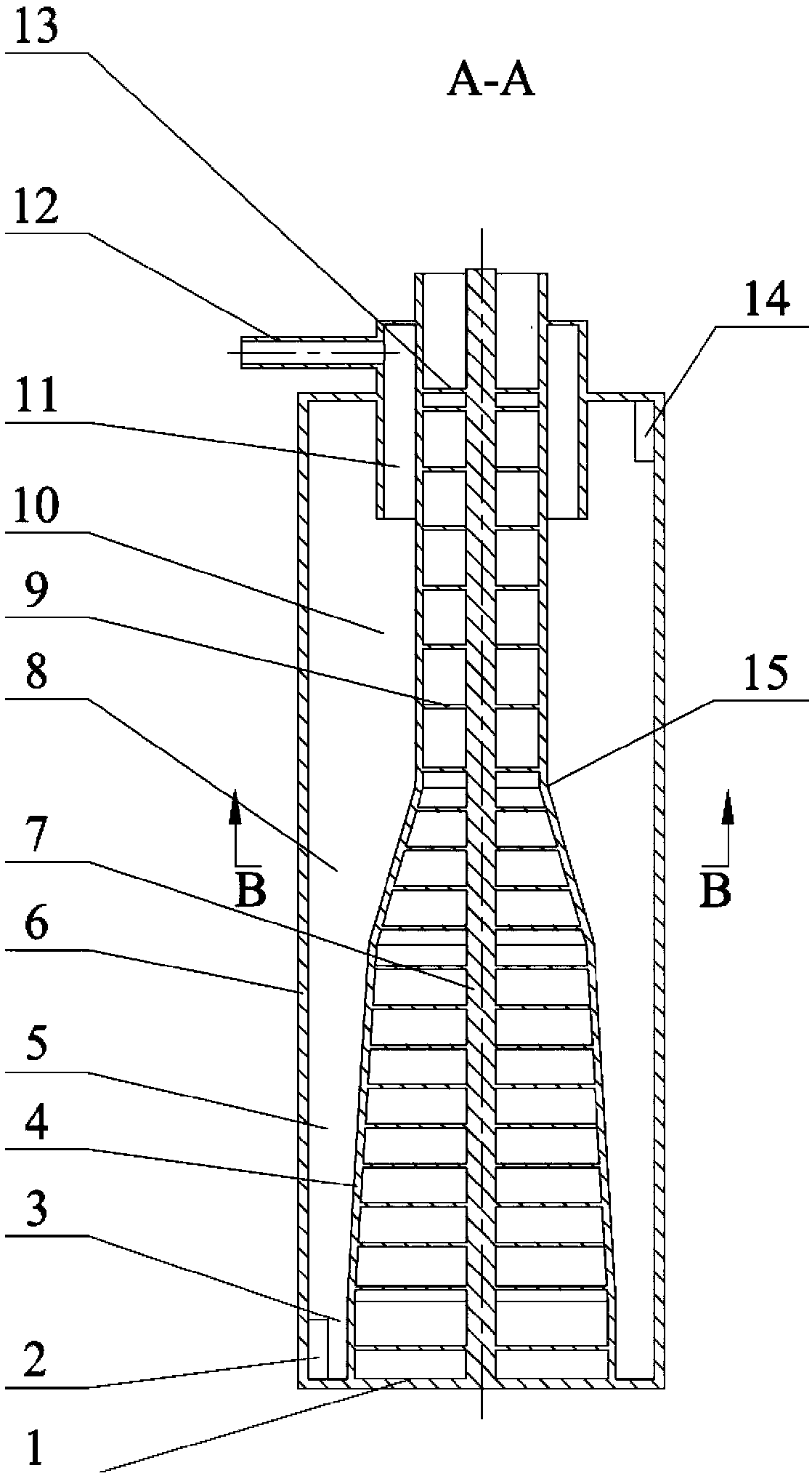
[0026] First, the purpose of the present invention is explained: in order to improve the separation efficiency of the existing hydrocyclone and expand the applicable range of the cyclone, a magnetic core hydrocyclone is designed. The main purposes are: (1) Improve the efficiency of cyclone separation processing; (2) Combine electromagnetic field with mechanical structure using complete physical method to provide new ideas for oil-water emulsion demulsification and separation, and promote the development of separation technology; ( 3) It can treat different types of oil-water mixtures, expand the application range of swirling separation, and can be widely used in crude oil dehydration, sewage degreasing, oil refinery slop oil recovery, automobile lubricating oil recovery and other fields.

[0027] In order to achieve the above objectives, the present invention first proposes a new method...


PUM


Abstract

A hydrocyclone separation method and device, and an electric power control method for an inner cylinder magnetic core. It is characterized in that: the inner cylinder of the cyclone is changed into an inner cylinder magnetic core that can generate magnetic force, artificially added magnetic particles whose density and particle size are close to the oil to be separated, and the water phase is separated into the cyclone by centrifugal force in the cyclone. While on the inner wall of the outer cylinder of the swirler, the inner cylinder magnetic core provides the magnetic force, the magnetic force is distributed from large to small along the radial direction of the cyclone, and distributed in steps along the axial direction of the cyclone, which will be related to the oil droplet density and particle size. Magnetic particles with equal diameters attract radially to the inner cylinder and drive oil droplets to move to the outer wall of the inner cylinder at the same time; the power control module supplies power to the magnetic pole group in the inner cylinder of the cyclone, and the timing of the single-chip microcomputer of the power control module adopts three-stage electromagnetic Cycle control. The magnetic core hydrocyclone provided by the invention can generate rotating centrifugal force and centripetal magnetic force at the same time, can accelerate the demulsification of oil-water emulsion and promote oil-water separation, improve the efficiency of cyclone separation, and solve the separation of complex oil-water mixed media question.

Description

Technical field [0001] The invention relates to a method and a device applied in the field of cyclone separation. Background technique [0002] The traditional oil-water separation cyclone uses the density difference between the oil and water phases for centrifugal separation. The oil-water mixture generally enters the cyclone in the tangential direction. In the high-speed rotating flow field, the heavy water phase faces the outer cylinder of the cyclone. Flow on the inner wall surface and finally discharged from the underflow port, and the light oil phase is forced to move to the center of the cyclone, forming an upward rotating internal swirling flow, and finally discharged from the overflow port. A certain oil-water density difference is a necessary condition for cyclonic separation. However, as oilfield exploitation enters the middle and late stages, the oil-water density difference between heavy oil and polymer-containing produced fluid is small, the viscosity of the oil-wat...

Claims


Application Information

Patent Timeline
Patent Type & Authority Patents(China)
IPC IPC(8): B04C9/00
CPCB04C9/00
Inventor 赵立新杨旭刘琳徐保蕊曹喜承蒋明虎
Owner NORTHEAST GASOLINEEUM UNIV
Why Eureka
Try Eureka