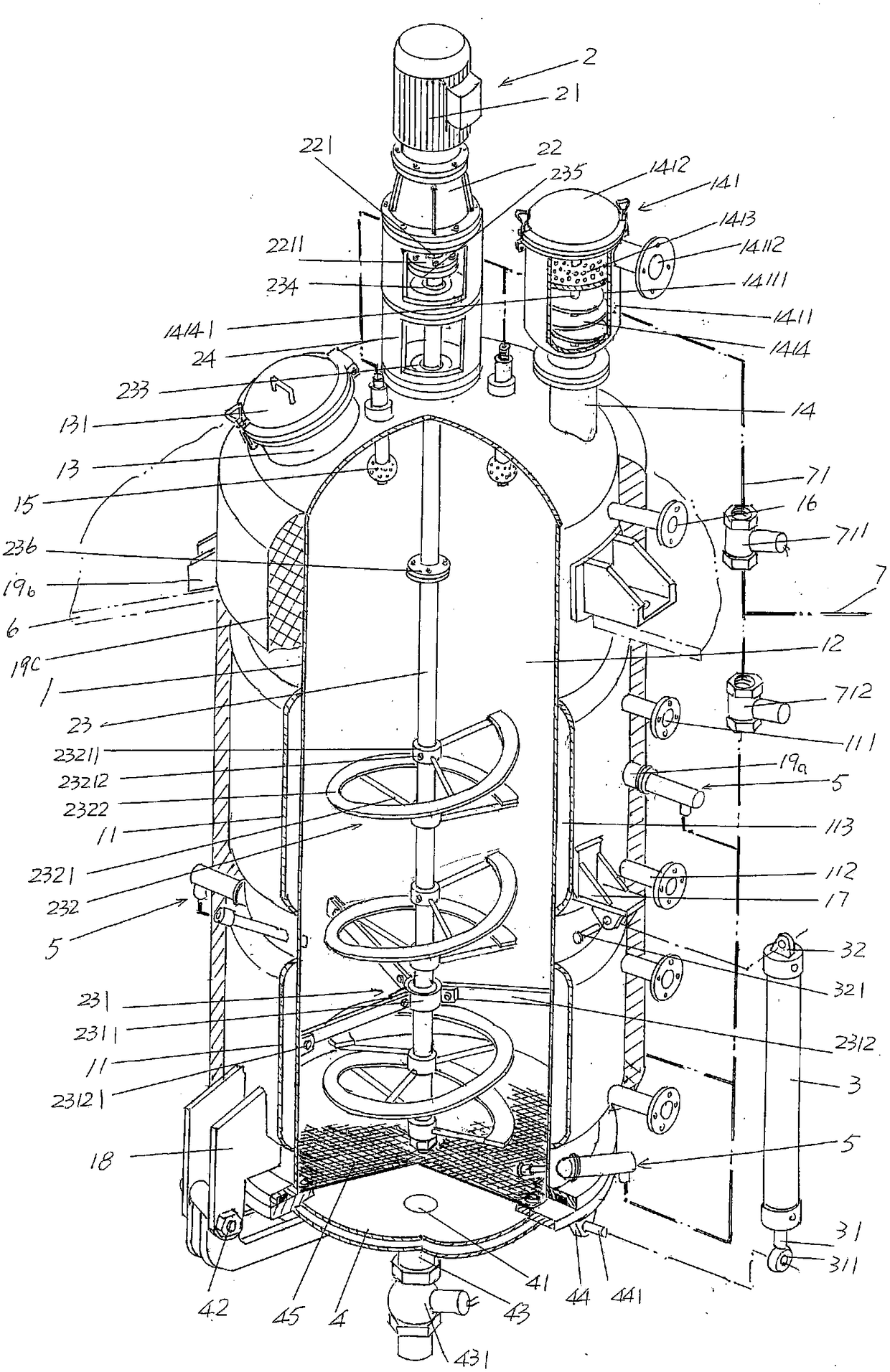
an extraction tank

A technology for extracting tanks and tanks, which is applied in the field of pharmaceutical machinery, can solve problems such as insufficient understanding, no specific structure of the cleaning device, and difficulty in guaranteeing the cleaning effect, etc., to meet the requirements of good interchangeability, avoid deformation, and reduce torque effect of influence

Active Publication Date: 2018-07-20
JIANGSU SHAJIABANG CHEM EQUIP
View PDF14 Cites 4 Cited by
  • Summary
  • Abstract
  • Description
  • Claims
  • Application Information

AI Technical Summary

Problems solved by technology

For example, the aforementioned CN101327381B, CN202777909U and CN102903225A are all equipped with a cleaning device, but neither CN101327381B nor CN105903225A provides the specific structure of the cleaning device, and those skilled in the art are not enough to comprehend the 6th line of paragraph 0012 of the description of CN101327381B by virtue of their professional knowledge The specific structure of the 360 ​​° rotating nozzle
Although CN202777909U describes the structure of the cleaning device in more detail (paragraph 0018 of the description), it is difficult to ensure the cleaning effect because the structural system of the cleaning device uses a traditional and static spray pipe, which cannot be rotated or retracted.

Method used


Image

  • an extraction tank
  • an extraction tank
  • an extraction tank

Examples


Embodiment Construction

[0022] In order to understand the technical essence and beneficial effects of the present invention more clearly, the applicant will describe in detail the following examples, but the descriptions of the examples are not intended to limit the solutions of the present invention. Equivalent transformations that are only formal but not substantive should be regarded as the scope of the technical solution of the present invention.

[0023] In the following descriptions, all concepts related to directionality or azimuth such as up, down, left, and right are aimed at the position state of the figure being described, and thus cannot be interpreted as providing a basis for the present invention. Special restrictions on technical solutions.

[0024] See figure 1 , shows a tank body 1 (that is, the extraction tank body, the same below), the outer wall of the tank body 1 is provided with a heating spacer 11 (there are two in this embodiment), and a heating spacer 11 is fitted with a A ...


PUM


Abstract

Disclosed is an extracting tank. The extracting tank comprises a tank body, a stirring mechanism, and a plurality of side-placed rinsing mechanisms, wherein a heating spacer bush is arranged at the outer wall of the tank body, a heating medium leading-in connector and a heating medium leading-out connector are arranged on the heating spacer bush, and the top of the tank body is provided with a feeding port and a demister connector; a stirring motor coordinates with a stirring decelerator, a stirring shaft is located in a tank body cavity, a stirring shaft support is fixed on the cavity wall of the tank body cavity, and the shaft body of the stirring shaft is provided with a stirring blade; an acting cylinder is arranged on the tank body, one side of a slag discharging gate is hinged to the tank body, the other side of the slag discharging gate is connected with the acting cylinder, and the center is provided with an extracting solution leading-out port; the side-placed rinsing mechanisms are arranged on the side wall of the tank body and stretch into the tank body cavity. The extracting tank is characterized in that the stirring blade is composed of a helical band supporting frame and a helical band, the helical band supporting frame is fixed to the stirring shaft, and the helical band is fixed on the helical band supporting frame and maintains certain distance from the stirring shaft and the cavity wall of the tank body cavity. In this way, requirements of interchanging between a cold zone and a hot zone are satisfied, and an effect of uniform temperature of a material is guaranteed; meanwhile, influence of moment of force on the stirring shaft and stress degree of the stirring shaft are lowered, and thus appearance of deformation can be avoided; in addition, the rinsing effect of the extracting tank is good.

Description

technical field [0001] The invention belongs to the technical field of pharmaceutical machinery, and in particular relates to an extraction tank. Background technique [0002] Extraction tanks are widely used in the pharmaceutical, chemical and even food production industries and are widely seen in published Chinese patent documents, such as CN1520797A (circulating dynamic extraction tank), CN101843988B (continuous extraction device), CN106215457A (ultrasonic Extraction tank), CN104815457B (cage dynamic forced extraction tank with secondary steam recovery function), CN104826358A (cage dynamic forced extraction tank), CN102600635B (traditional Chinese medicine extraction tank), CN101327381B (ultrasonic conical three-part slag discharge extraction tank ), CN202777909U (spray type extraction tank) and CN105903225A (a silybin extraction tank with self-cleaning function), etc. [0003] Although not limited to the extraction tanks disclosed in the patents cited above, although ea...

Claims


Application Information

Patent Timeline
Patent Type & Authority Patents(China)
IPC IPC(8): B01D11/02B08B9/093
CPCB01D11/0223B08B9/093B08B9/0936
Inventor 汤大卫盛晓平余勤王仕超
Owner JIANGSU SHAJIABANG CHEM EQUIP
Why Eureka
Try Eureka