
Mobile air conditioner

An air conditioner and condenser technology, applied in air conditioning systems, space heating and ventilation, household heating, etc., can solve the wear and tear of the air outlet frame and casing, reduce the service life of mobile air conditioners, and prevent the air outlet frame from rotating and other problems to achieve the effect of smooth rotation, improved stability and safety, and reduced wear

Inactive Publication Date: 2017-04-19
HANDAN MIDEA REFRIGERATION EQUIP +1
View PDF6 Cites 5 Cited by
  • Summary
  • Abstract
  • Description
  • Claims
  • Application Information

AI Technical Summary

Problems solved by technology

[0003] (1) The technical problem to be solved by the present invention is: the friction between the air outlet frame of the existing air conditioner and the upper end of the casing is relatively large, which may easily cause the wear of the air outlet frame and the casing, resulting in the failure of the air outlet frame to rotate , but also reduces the service life of the mobile air conditioner

Method used


Image

  • Mobile air conditioner
  • Mobile air conditioner
  • Mobile air conditioner

Examples


Embodiment 1

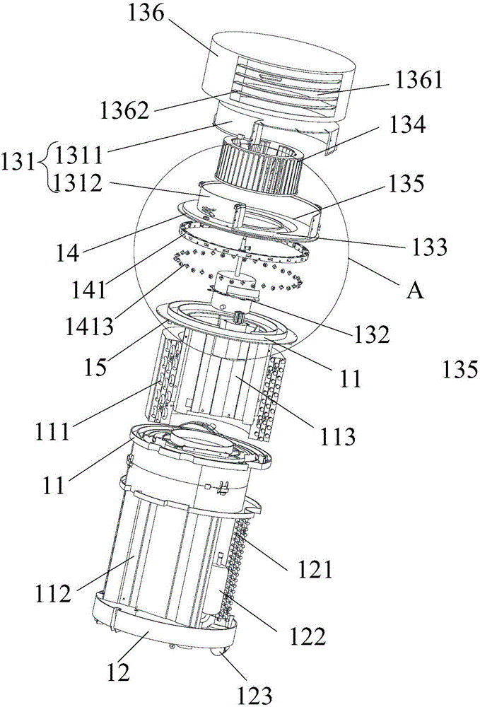
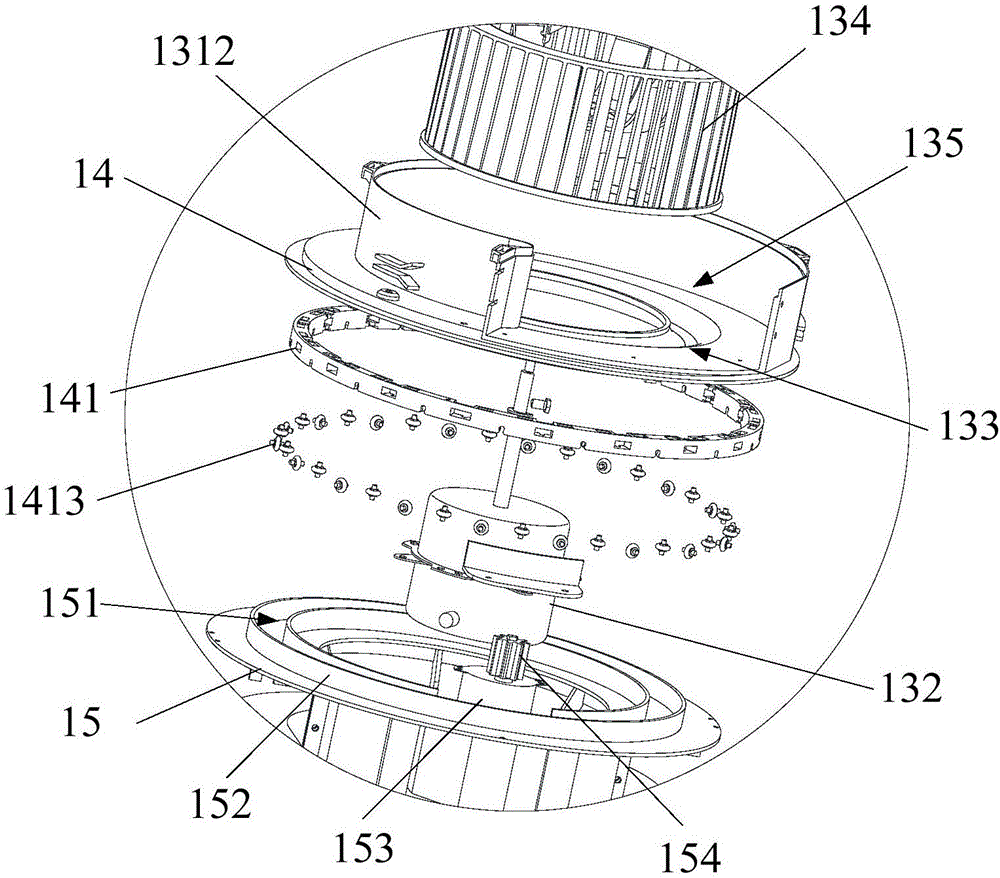
[0030] like figure 1As shown, this embodiment provides a mobile air conditioner, including a base 12, a casing, a compressor 122, a condenser 121, a capillary tube and an evaporator 111, the casing is cylindrical and fixed on the base 12, The interior of the housing forms a housing chamber, the compressor 122, condenser 121, capillary tube and evaporator 111 are all located in the housing chamber and communicated in sequence to form a closed loop, the upper end of the housing is provided with an air outlet mechanism 13, so The air outlet mechanism 13 is rotatably connected with the casing through a turntable 14, as figure 1 and figure 2 As shown, the lower end of the turntable 14 is provided with a roller 1413, so that the sliding connection between the turntable 14 and the upper end of the casing is changed from a sliding connection to a rolling connection, which reduces the friction between the turntable 14 and the casing, thereby reducing the air outlet mechanism 13. Due...

Embodiment 2

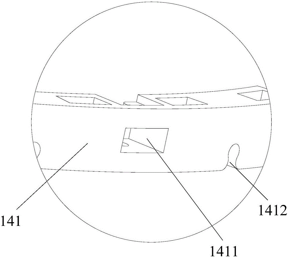
[0041] This embodiment is substantially the same as the technical solution in Embodiment 1, the main difference is that, as figure 1As shown, in this embodiment, the lower end of the turntable 14 and the circumferential direction of the outer wall are provided with the rollers 1413, specifically, the upper end surface of the casing upper cover 15 is provided with an annular slideway 151, and the turntable The lower end of 14 is provided with an annular first projection 141 matched with the annular slideway 151, and the first projection 141 can rotate around the axis of the turntable 14 in the annular slideway 151. The upper end of the casing loamer 15 is provided with two coaxial annular vertical plates 152, and the slideway 151 is formed between the two annular vertical plates 152, and the slideway 151 is provided with a drive for driving the turntable 14. The driving mechanism of rotation; said roller 1413 is arranged on the outer wall surface of the lower end of said first ...


PUM


Abstract

The invention relates to the technical field of household electrical appliances, in particular to a mobile air conditioner. The mobile air conditioner provided by the invention comprises a base, a machine enclosure, a compressor, a condenser, a capillary tube and an evaporator. Compared with an existing mobile air conditioner, the mobile air conditioner provided by the invention has the advantages that a plurality of rollers are arranged at the lower end of a rotary disc and / or in the circumferential direction of the side wall of the rotary disc, so that the rotary disc and the upper end of the machine enclosure are changed into rolling connection from sliding connection, and friction between the rotary disc and the machine enclosure is reduced, and therefore, abrasion between an air outlet mechanism and the machine enclosure is reduced, an air outlet frame rotates more stably, stability and safety of operation of the air conditioner are improved, and the service life of the air conditioner is also prolonged.

Description

technical field [0001] The invention relates to the technical field of household appliances, in particular to a mobile air conditioner. Background technique [0002] Generally, an air conditioner is a device that cools or heats an indoor environment to create a comfortable indoor environment, and is roughly classified into an integrated type air conditioner and a split type air conditioner. Although the functions of the integrated air conditioner and the split air conditioner are the same, the integrated air conditioner is equipped with cooling and heat dissipation components in the same casing, and is installed on the wall or on the window through the wall. The air conditioner is the most common integrated air conditioner, while the split air conditioner is composed of an indoor unit and an outdoor unit. The indoor unit is equipped with a cooling device, and the outdoor unit is equipped with a heat dissipation and compression device. The indoor unit and the outdoor unit are...

Claims


Application Information

Patent Timeline
Patent Type & Authority Applications(China)
IPC IPC(8): F24F1/02F24F13/10F24F13/20
CPCF24F1/022F24F13/10F24F13/20F24F2221/125
Inventor 何军贤江敬强刘士军
Owner HANDAN MIDEA REFRIGERATION EQUIP
Learn More