
Punch used for stamping die

A technology of stamping dies and punches, applied in the field of molds, can solve the problems of poor wear resistance of punches, achieve good cooling, good lubrication, and improve processing quality

Inactive Publication Date: 2017-03-29
TIANJIN HAOXIN PRECISION MOLD
View PDF1 Cites 0 Cited by
  • Summary
  • Abstract
  • Description
  • Claims
  • Application Information

AI Technical Summary

Problems solved by technology

[0003] Traditional punches have poor wear resistance and need to be replaced frequently

Method used


Image

  • Punch used for stamping die
  • Punch used for stamping die

Examples


Embodiment Construction

[0019] The present invention will be further described in detail below in conjunction with the accompanying drawings and through specific embodiments.

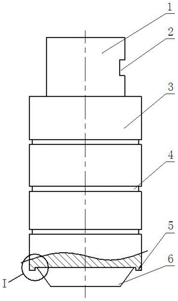
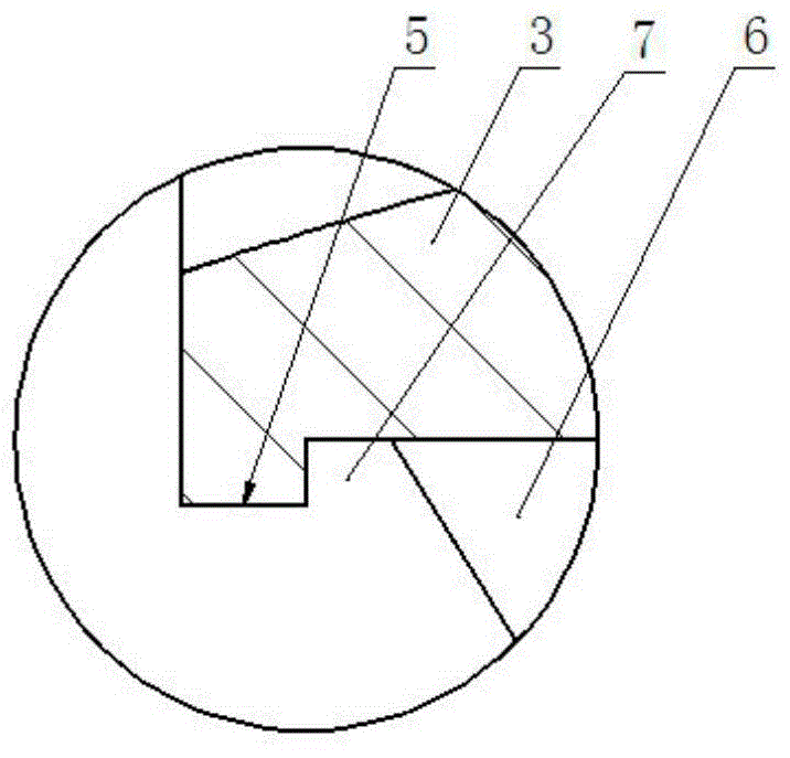
[0020] A punch used in stamping dies such as figure 1 As shown, the upper part of the body 3 of the punch is coaxially formed with a handle section 1, and the lower part of the body is coaxially formed with a transition section 6. The transition section is a frustum-shaped structure, which improves the positioning accuracy of the punch when punching. ; The outer edge of the lower end surface of the body is integrally formed with an annular boss 5 downwards, such as figure 2 As shown, an annular groove 7 is formed between the annular boss and the transition section, and coolant can be stored in the annular groove to avoid cracking or surface strain of the punch due to thermal fatigue and prolong the service life.

[0021] In this embodiment, the outer edge of the body is uniformly spaced and coaxially formed with a plurality ...


PUM


Abstract

The invention relates to a punch used for a stamping die. The upper part of a body of the punch is integrally and coaxially provided with a handle section. The lower part of the body of the punch is integrally and coaxially provided with a transition section. The outer edge of the lower end surface of the body is integrally and downwardly provided with an annular boss. An annular groove is formed between the annular boss and the transition section. The outer edge of the body is uniformly and coaxially provided with multiple annular grooves at intervals. The punch used for the stamping die has following beneficial effects: due to the fact that the lower end surface of the body of the punch is integrally and downwardly provided with the annular boss, and the annular groove is formed between the annular boss and the transition section, the annular groove can store cooling liquid so that crack or surface strain of the punch caused by excessive heat can be avoided, thereby prolonging service lifetime; good cooling and lubrication effects of the punch are ensured; crack or surface strain caused by excessive heat is avoided; and the punch is featured by being high in location precision and long in service lifetime.

Description

technical field [0001] The invention belongs to the technical field of dies, in particular to a punch used for stamping dies. Background technique [0002] In the processing of hardware products, stamping is a conventional technical means. When stamping, the material to be stamped is placed on the mold, and the punch is used to stamp the material. [0003] Traditional punches have poor wear resistance and need to be replaced frequently. [0004] After searching, I found a Chinese patent publication similar to this patent application, a punching head, announcement number: CN202893964U, including a cylindrical punch body (1), the bottom edge of the punch body (1) There is a chamfer (3), the center of the bottom of the punch body (1) is provided with a positioning cone (2) integrally formed with the punch body (1), and the positioning cone (2) is provided with a layer of wear-resistant coating Floor. [0005] After comparison, it is found that the technical solution of this ...

Claims


Application Information

Patent Timeline
Patent Type & Authority Applications(China)
IPC IPC(8): B21D37/10B21D37/16B21D37/18
Inventor 赵化见
Owner TIANJIN HAOXIN PRECISION MOLD
Learn More