Dehumidifying and cooling apparatus

一种制冷设备、除湿机的技术,应用在机械设备、照明和加热设备、加热方式等方向,能够解决增加电耗等问题,达到降低功耗、改善内部除湿制冷效果、改善内部通风效果的效果

Active Publication Date: 2017-03-22
KYUNGDONG NAVIEN
View PDF9 Cites 0 Cited by
  • Summary
  • Abstract
  • Description
  • Claims
  • Application Information

AI Technical Summary

Problems solved by technology

For this reason, the usual dehumidification refrigeration equipment also has the disadvantage of increasing power consumption

Method used


Image

  • Dehumidifying and cooling apparatus
  • Dehumidifying and cooling apparatus
  • Dehumidifying and cooling apparatus

Examples


Embodiment Construction

[0060] Hereinafter, a dehumidification refrigeration apparatus according to an exemplary embodiment of the present invention will be described in detail with reference to the accompanying drawings. However, the same components in different implementations will only be described in detail in one of the implementations, and repeated descriptions will be omitted in the remaining implementations.

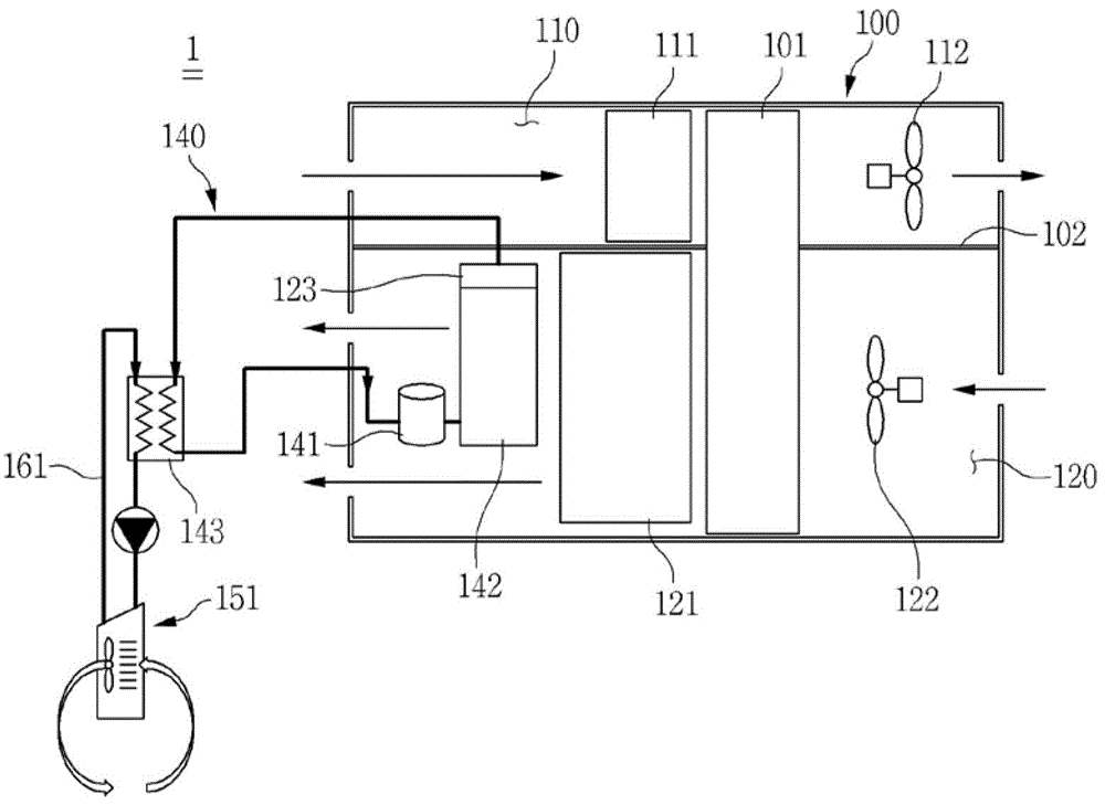
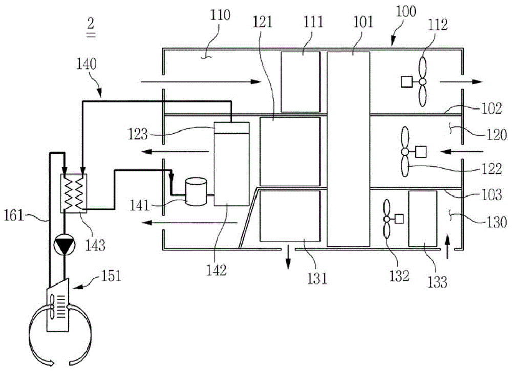
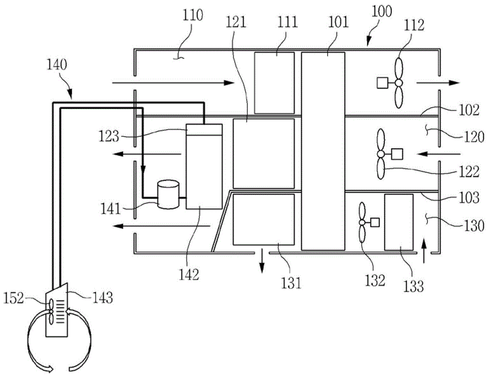
[0061] figure 1 is a structural block diagram of the dehumidification and refrigeration equipment according to the first embodiment of the present invention. figure 2 is a structural block diagram of the dehumidification and refrigeration equipment according to the second embodiment of the present invention. image 3 is a structural block diagram of a dehumidification refrigeration device according to a third embodiment of the present invention. Figure 4 is a structural block diagram of a dehumidification refrigeration device according to a fourth embodiment of the present invention...


PUM


Abstract

The present invention relates to a dehumidifying and cooling apparatus, comprising a housing in which a first channel and a second channel are formed; a heating unit disposed inside the first channel; a dehumidifying rotor which is rotatably provided inside the housing; a cooling unit disposed inside the second channel; and a refrigerant circulation unit having a refrigerant circulation circuit including a compressor and a condenser, wherein the condenser is disposed inside the second channel such that the refrigerant circulated therein, can be condensed by the heat exchange with the second air cooled by the cooling unit.

Description

technical field [0001] The present invention relates to a dehumidification refrigeration equipment which can be connected to a panel refrigeration equipment, or a refrigeration equipment or an electric air conditioner using a fan coil unit, so that it can also be used in a structure in which no air circulation pipe fittings for refrigeration are assembled , thus improving internal cooling efficiency. Background technique [0002] Desiccant cooling is a technique for cooling by controlling the latent heat load that is cooled by a dehumidifier and using the heat of evaporation. [0003] In more detail, the dehumidification refrigeration technology performs the process of lowering the temperature of the air using evaporation heat by removing moisture contained in the air by using a dehumidifier, and evaporating the dehumidified and dried air by supplying moisture thereto , Refrigeration is also performed by repeating the above process by forming a cycle. [0004] In terms of ...

Claims


Application Information

Patent Timeline
Patent Type & Authority Applications(China)
IPC IPC(8): F24F3/12F24F3/14
CPCF24F3/12F24F3/14F24F11/77F24F3/1423F24F2203/1016F24F2203/1032Y02B30/70F24F3/153F24F2003/144F24F2203/1068
Inventor 李东根
Owner KYUNGDONG NAVIEN
Why Eureka
Try Eureka