
Cooling shaft piston

A technology for cooling shafts and pistons, which is applied to liquid variable displacement machines, variable displacement pump components, machines/engines, etc., and can solve the problems of reducing the working efficiency of pistons, increasing the amount of coolant, and low cooling efficiency

Active Publication Date: 2020-02-04
SHENYANG LIGONG UNIV
View PDF5 Cites 0 Cited by
  • Summary
  • Abstract
  • Description
  • Claims
  • Application Information

AI Technical Summary

Problems solved by technology

Traditional piston cooling methods such as free spray cooling without oil chamber, serpentine tube circulation cooling, and vibration cooling cannot achieve the ideal cooling effect
Cooling means heat loss, but this loss is necessary to keep the piston working properly
If the piston is overcooled, it will have the following adverse effects: 1) too much heat loss, reducing the working efficiency of the piston; 2) too large temperature difference, too high thermal stress; 3) increasing the amount of coolant, increasing the cost
Moreover, the traditional piston cooling method is mostly external cavity cooling, the cooling efficiency is low, and the cooling cost is high

Method used


Image

  • Cooling shaft piston
  • Cooling shaft piston
  • Cooling shaft piston

Examples


Embodiment Construction

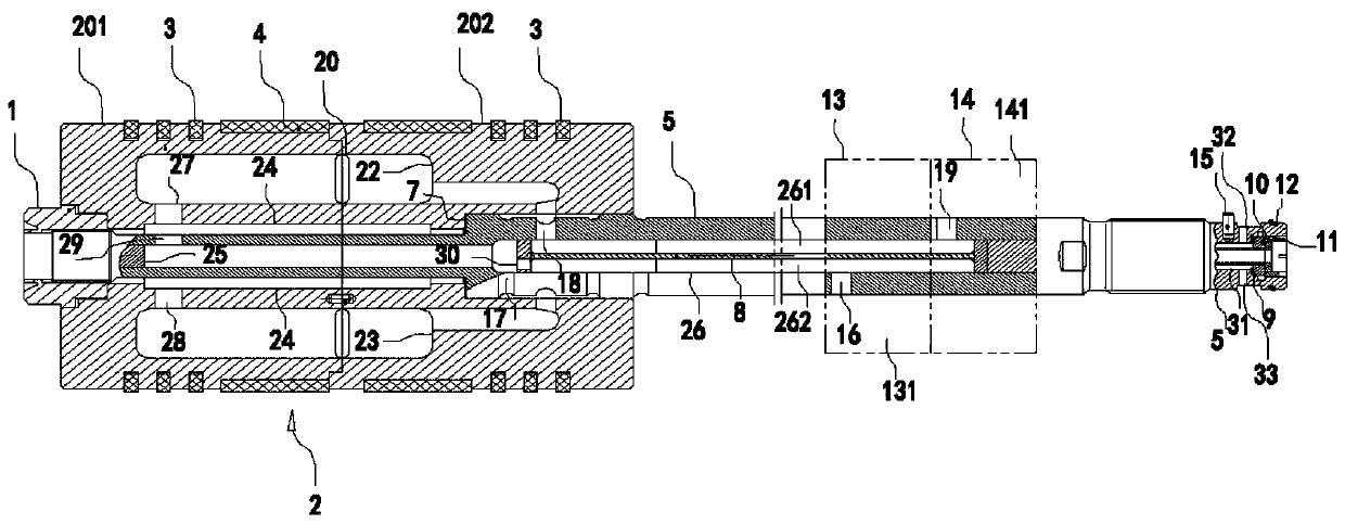
[0023] Such as figure 1 and figure 2 As shown, the cooling shaft piston includes a piston body 2, a piston rod body 5, a first sealed double compartment 13 and a second sealed double compartment 14;

[0024] The piston body 2 includes a front half piston body 201 and a rear half piston body 202; the ends of the front half piston body 201 and the rear half piston body 202 are fixedly connected horizontally; inside the piston body 2, they are respectively symmetrical up and down An upper piston body cavity 22 and a lower piston body cavity 23 are provided; a piston rod body assembly channel 24 is arranged laterally in the middle region of the piston body 2; The front end of 201 is fixedly connected;

[0025] The inside of the piston rod body 5 is horizontally provided with a rod body front end cavity 25 and a rod body rear end cavity 26 in turn; a piston rod core 8 is horizontally fixed in the rod body rear end cavity 26 to form upper and rear ends independent of each other. ...


PUM


Abstract

The invention belongs to the field of reciprocating compressor accessories, and particularly relates to a cooling shaft piston. The cooling shaft piston comprises a piston body (2), a piston rod body(5), a first sealed double compartment (13) and a second sealed double compartment (14), wherein the piston body (2) comprises a front semi-piston body (201) and a rear semi-piston body (202); an upper piston body cavity (22) and a lower piston body cavity (23) are symmetrically arranged inside the piston body (2) in an up-and-down sequence; the first sealed double compartment (13) and the secondsealed double compartment (14) are arranged on the right side of the piston body (2); and the piston rod body (5) passes through the first sealed double compartment (13) and the second sealed double compartment (14) and movably cooperates with the first sealed double compartment (13) and the second sealed double compartment (14). According to the cooling shaft piston, multiple paths of circulationof a cooling medium can be formed in the piston body, the piston rod body, the first sealed double-compartment and the second sealed double-compartment, so that internal cooling inside a piston connecting rod is realized, and high cooling efficiency and low production cost can be achieved.

Description

technical field [0001] The invention belongs to the field of accessories for reciprocating compressors, in particular to a cooling shaft piston. Background technique [0002] During the design process of reciprocating compressors, the cooling design of the piston is very important. Traditional piston cooling methods such as free spray cooling without oil chamber, serpentine tube circulation cooling, and vibration cooling cannot achieve the ideal cooling effect. Cooling means heat loss, but this loss is necessary to keep the pistons working properly. If the piston is overcooled, it will have the following adverse effects: 1) too much heat loss, reducing the working efficiency of the piston; 2) too large temperature difference, too high thermal stress; 3) increasing the amount of coolant, increasing the cost. Moreover, the traditional piston cooling method is mostly external cavity cooling, which has low cooling efficiency and high cooling cost. Contents of the invention ...

Claims


Application Information

Patent Timeline
IPC IPC(8): F04B39/06F04B39/00
CPCF04B39/00F04B39/0005F04B39/06
Inventor 巴鹏江泽磊巴和平
Owner SHENYANG LIGONG UNIV
Learn More