Screw conveying mechanism

A conveying mechanism and screw technology, applied in metal processing, metal processing equipment, manufacturing tools, etc., can solve the problems of inability to convey in a direction, low conveying efficiency, poor conveying effect, etc., to reduce the probability of overturning, good conveying effect, The effect of improving reliability

Active Publication Date: 2017-03-22
SHENZHEN SKYWORTH RGB ELECTRONICS CO LTD +1
View PDF9 Cites 4 Cited by
  • Summary
  • Abstract
  • Description
  • Claims
  • Application Information

AI Technical Summary

Problems solved by technology

However, for short and wide screws, because the length is not enough to limit its direction in the plastic hose, it will turn over at random during the movement of the plastic hose, and cannot be transported according to the direction, and finally output from the discharge end of the plastic hose The direction of the screws is messy, resulting in low conveying efficiency, poor conveying effect, increased labor costs, and inconvenient use

Method used


Image

  • Screw conveying mechanism
  • Screw conveying mechanism
  • Screw conveying mechanism

Examples


Embodiment 1

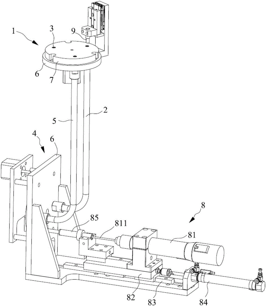
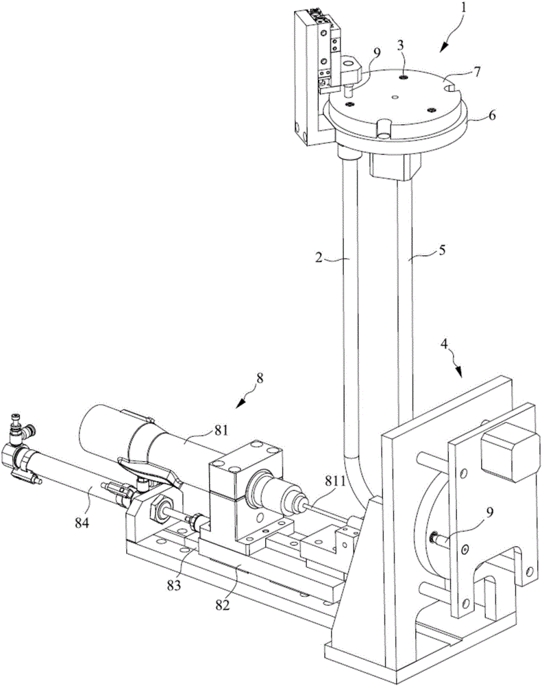
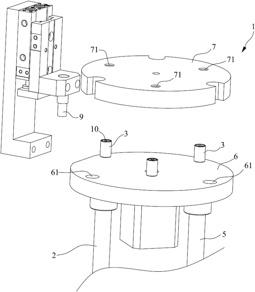
[0027] Such as Figure 1-Figure 6 As shown, this embodiment provides a screw conveying mechanism, including a feeding device 1, a feeding tube 2 and a conveying member 3 for conveying the screw 10. The feeding device 1 can be a plate structure, a block structure or other The feeding device 1 is provided with a material plate hole 71 communicating with the feeding pipe 2, and the conveying part 3 is located in the material plate hole 71 and can enter into the feeding pipe 2 and move along the feeding pipe 2. The feeding pipe 2 is in the feeding device. One end of 1 can be connected with an air blowing device, the conveying part 3 includes a housing chamber 31, and the screw 10 is fixed in the housing chamber 31, and the ratio of the longitudinal dimension to the transverse dimension of the conveying part prevents the conveying part from overturning when moving in the feeding tube. Generally speaking, when the ratio of the height to width of the conveying member 3 is not less th...


PUM


Abstract

The invention discloses a screw conveying mechanism. The mechanism comprises a feeding device, a feeding pipe and conveying pieces for conveying screws; material plate holes communicating with the feeding pipe are formed in the feeding device; the conveying pieces can enter the feeding pipe via the material plate holes and can move along the feeding pipe; each conveying piece comprises an accommodating cavity; the screws are fixed in the accommodating cavities; and the conveying pieces cannot be turned over when moving in the feeding pipe due to the ratio of the longitudinal size to the transverse size of the conveying pieces. The conveying pieces can be conveyed in a fixed direction, and the screws are fixed in the conveying pieces, so that the screws can also be conveyed in the fixed direction. The screw conveying mechanism is suitable for conveying of the screws in any models, all that is required is to change the corresponding conveying pieces according to the screws, the conveying effect is good, and the universality is high.

Description

technical field [0001] The invention relates to the technical field of screw delivery, in particular to a screw delivery mechanism. Background technique [0002] The screw conveyor is used to convey the screws to the station where the screws need to be fastened. The existing screw conveying mechanism is mainly conveyed through the plastic hose. The discharge end of the plastic hose can be blown into the plastic hose. After putting the screw into the plastic hose, blow air through the blowing device to make the screw move along the plastic hose to the position where the screw is needed. For the ratio of screw length to nut diameter ≥ 1.2, especially long and narrow screws ≥ 1.3, this delivery method will not cause the direction of the screw to change, and the delivery is more convenient. But for short and wide screws, because the length is not enough to limit its direction in the plastic hose, it will turn over at random during the movement of the plastic hose, and cannot be...

Claims


Application Information

Patent Timeline
IPC IPC(8): B23P19/00B23P19/06
CPCB23P19/002B23P19/06
Inventor 罗铭叶闯杨军治
Owner SHENZHEN SKYWORTH RGB ELECTRONICS CO LTD
Why Eureka
Try Eureka