
Welding gun pose-variable closed geometric component GMAW added material manufacturing method

A technology of additive manufacturing and welding torch, which is applied in the field of additive manufacturing of metal components, can solve problems such as molten pool flowing easily, difficult to control forming, and difficult to form closed geometric components, etc., to overcome insufficient forming ability, improve quality, and simple operation Effect

Inactive Publication Date: 2017-03-22
SOUTHWEST JIAOTONG UNIV
View PDF3 Cites 8 Cited by
  • Summary
  • Abstract
  • Description
  • Claims
  • Application Information

AI Technical Summary

Problems solved by technology

When the forming angle is small, it is difficult for the molten pool to solidify in time on the current forming layer and it is easy to flow, and the forming is difficult to control or even collapses
At present, the manufacturing of geometric components with non-closed paths can be realized by using the welding torch perpendicular to the horizontal plane and the positioner to drive the substrate to turn over, but this method is difficult to form closed geometric components
In addition, there is another way to form inclined geometric parts by using the welding torch to offset laterally perpendicular to the horizontal plane, but this method has insufficient ability to form inclined surfaces

Method used


Image

  • Welding gun pose-variable closed geometric component GMAW added material manufacturing method
  • Welding gun pose-variable closed geometric component GMAW added material manufacturing method

Examples


Embodiment 1

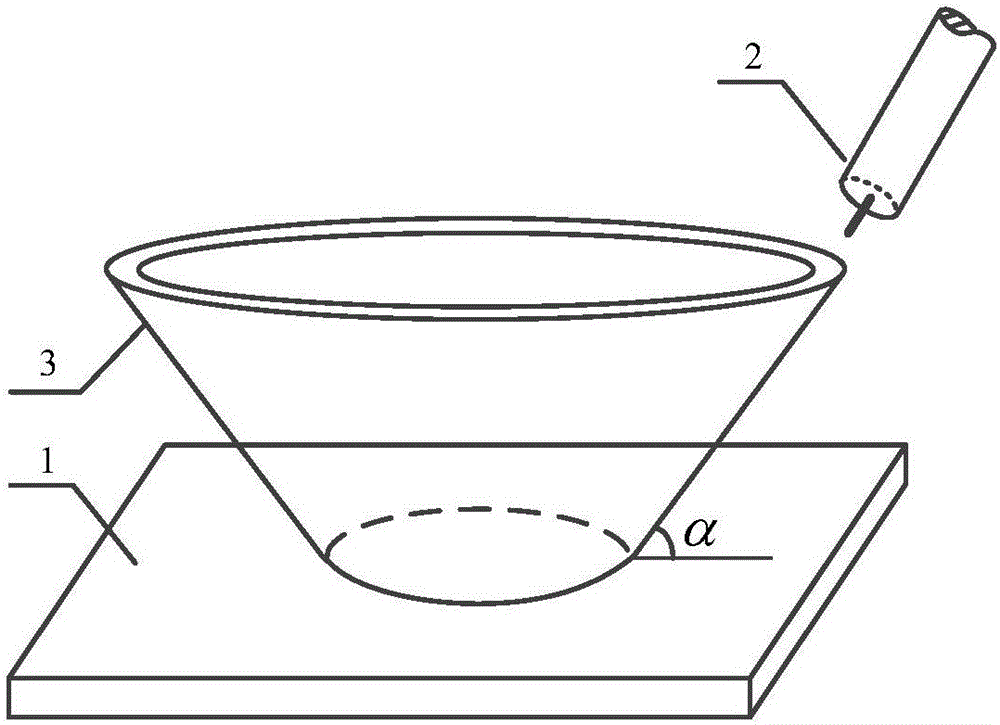
[0032] Such as figure 1 As shown, the SMA490BW high-strength steel straight-wall closed geometric component 3 has a height of 70mm, a bottom inner diameter of 80mm, and an outer diameter of 90mm. The angle α formed by the growth direction of the component and its projection on the substrate plane is 10°. It adopts the closed geometric component GMAW additive manufacturing method of variable welding torch position and posture described in the present invention, and the specific steps are as follows:

[0033] Step 1: According to figure 1 For the three-dimensional size and structure of the closed geometric component 3 shown, its Solidworks model is established in the three-dimensional modeling software, the STL model constructed by the closed geometry is extracted and sliced ​​layer by layer, and the corresponding forming path is determined.

[0034] Step 2: Complete the mechanical grinding of the first layer of the forming path on the substrate 1 and the surrounding 15mm area,...

Embodiment 2

[0040] A closed geometric component whose outer contour is a curve is 50mm high, the inner diameter of the bottom is 95mm, and the outer diameter is 105mm. The closed geometric component is a multi-layer single-channel thin-walled part connected end to end, and the growth direction of the shaping layer is determined by its projection on the substrate plane. The angle formed is less than or equal to 90°, and the angle formed by the growth direction of the closed geometric component and its projection on the substrate plane changes with the outer contour of the closed geometric component. It adopts the closed geometric component GMAW additive manufacturing method of variable welding torch position and posture described in the present invention, and the specific steps are as follows:

[0041] Step 1: According to the three-dimensional size and structure of the closed geometric component, establish its Solidworks model in the three-dimensional modeling software, extract the STL mod...


PUM

PropertyMeasurementUnit
Outer diameteraaaaaaaaaa

Abstract

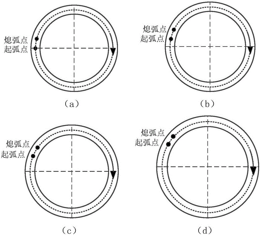
The invention provides a welding gun pose-variable closed geometric component GMAW added material manufacturing method. A closed geometric component consists of multiple layers of single-way thin-wall pieces connected end to end; an angle between the growth direction of a forming layer and a projection thereof on a substrate plane is smaller than and equal to 90 degrees; the method adopts a method for controlling the arc starting and quenching end joint quantity of the forming layer to improve the forming quality in the end-to-end connecting place; in the forming process, a welding gun gesture is adjusted to enable a welding gun to always point to the growth direction of the forming layer; and the generated arc force and plasma current force direction is parallel to the growth direction of the forming layer, so that the improvement of the stability of a molten pool of the forming layer is facilitated, and the large-dip-angle growth of the forming layer is realized. The method effectively overcomes the difficulties of weak forming quality of the end-to-end connecting place of the closed geometric component and low inclined surface forming capacity, is simple in operation, and is easy to realize automation of the GMAW added material manufacturing process.

Description

technical field [0001] The invention belongs to the technical field of additive manufacturing of metal components, in particular to a gas metal arc welding (GMAW) additive manufacturing method for a closed geometric component with variable welding gun position and posture. Background technique [0002] Closed geometric components are typical end-to-end structural parts, such as combustion chambers, missile casings and other key aviation and aerospace components. These parts have relatively large surface contour dimensions and thickness, and have strong bearing capacity. At present, the traditional method used to manufacture this kind of structural parts has the obvious disadvantage of low utilization rate of raw materials. In recent years, with the development of high-efficiency manufacturing, the requirements for the manufacturing cost and cycle of such metal parts have become more stringent. Additive manufacturing technology can quickly and accurately manufacture objects ...

Claims


Application Information

Patent Timeline
IPC IPC(8): B23K9/04B23K9/173B23K9/235B23K9/095B23K101/04
CPCB23K9/04B23K9/046B23K9/095B23K9/173B23K9/235B23K2101/04
Inventor 熊俊雷洋洋李蓉陈辉
Owner SOUTHWEST JIAOTONG UNIV
Learn More