
Signal-noise-ratio-post-filtering-and-characteristic-space-fusion minimum-variance ultrasonic imaging method

An ultrasonic imaging method and a technique of minimum variance, applied in ultrasonic/acoustic/infrasonic diagnosis, image enhancement, acoustic diagnosis, etc., can solve problems such as not being able to significantly improve image contrast and resolution

Active Publication Date: 2017-03-22
CHONGQING UNIV +1
View PDF1 Cites 15 Cited by
  • Summary
  • Abstract
  • Description
  • Claims
  • Application Information

AI Technical Summary

Problems solved by technology

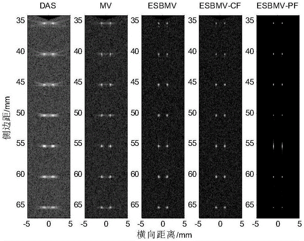
[0006] In view of this, the object of the present invention is to provide a minimum variance ultrasonic imaging algorithm for post-signal-to-noise ratio filtering and feature space fusion, which can improve image resolution, contrast and waveform formation robustness under low signal-to-noise ratio conditions , which effectively overcomes the problem that the traditional adaptive beamforming algorithm cannot significantly improve the image contrast and resolution under the condition of low signal-to-noise ratio, thus comprehensively improving the overall quality of ultrasound images

Method used


Image

  • Signal-noise-ratio-post-filtering-and-characteristic-space-fusion minimum-variance ultrasonic imaging method
  • Signal-noise-ratio-post-filtering-and-characteristic-space-fusion minimum-variance ultrasonic imaging method
  • Signal-noise-ratio-post-filtering-and-characteristic-space-fusion minimum-variance ultrasonic imaging method

Examples


Embodiment Construction

[0062] The preferred embodiments of the present invention will be described in detail below with reference to the accompanying drawings.

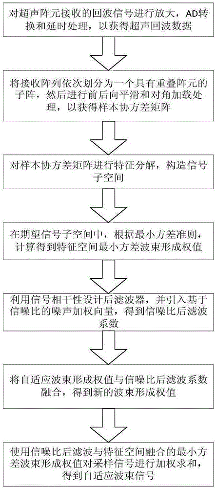
[0063] figure 1 It is an algorithm flow chart of the present invention, as shown in the figure, the present invention provides a minimum variance ultrasonic imaging algorithm for signal-to-noise ratio post-filtering and feature space fusion, including the following steps:

[0064] Step S1: Amplify and AD convert the echo signal and perform delay focus processing to obtain the signal x(k) after focus delay processing, and x(k) is expressed as x(k)=[x 1 (k),x 2 (k),...,x N (k)], where N represents the number of array elements of the ultrasonic array, and k represents the sampling moment corresponding to the sampling depth.

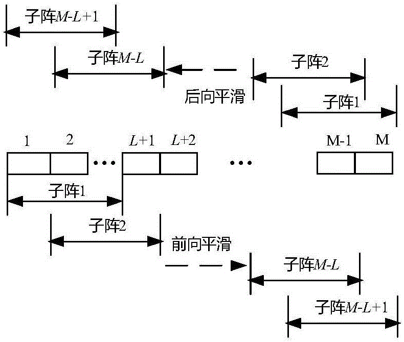
[0065] Step S2: The receiving array is sequentially divided into a sub-array with overlapping array elements, and then the echo signals of the corresponding receiving sub-array are subjected to forward-backward smoothi...


PUM


Abstract

The invention relates to a signal-noise-ratio-post-filtering-and-characteristic-space-fusion minimum-variance ultrasonic imaging method. The signal-noise-ratio-post-filtering-and-characteristic-space-fusion minimum-variance ultrasonic imaging method includes the steps that sampling signals received by array elements are delayed, subjected to forward-backward smoothing and subjected to diagonal loading treatment, and an estimated sample covariance matrix is obtained; the estimated covariance matrix is subjected to characteristic decomposition, and signal subspace is constructed; in the desired signal subspace, according to the minimum-variance criterion, an adaptive beam-forming weight value is calculated; then a post-filtering coefficient is designed according to the signal coherence, a noise weighting coefficient is introduced according to the input signal noise ratio, and a signal-noise-ratio-filtering coefficient is calculated; the adaptive beam-forming weight value and the signal-noise-ratio-filtering coefficient are fused to obtain the novel weight vector; finally, multiple pieces of data subjected to forward-backward smoothing treatment are weighted and summed through the obtained minimum-variance weight value fusing the signal-noise-ratio post filtering and the characteristic space, and an adaptive beam signal is obtained. By means of the signal-noise-ratio-post-filtering-and-characteristic-space-fusion minimum-variance ultrasonic imaging method, the properties of ultrasonic images in the resolution ratio aspect, the contrast ratio aspect, the noise robustness aspect and the like can be improved, and therefore the quality of ultrasonic imaging is improved as a whole.

Description

technical field [0001] The invention belongs to the technical field of ultrasonic imaging, and relates to a minimum variance ultrasonic imaging method of signal-to-noise ratio post-filtering and feature space fusion. Background technique [0002] The most widely used and simplest beamforming technology in ultrasonic imaging is DelayAnd Sum (DAS), which calculates the delay amount of the received echo signal according to the geometric position relationship of the array element channel. Then align and superimpose the delayed data. The traditional DAS algorithm has low complexity and fast imaging speed, but the width of the main lobe is increased and the resolution is low due to the weighting of the fixed window function. [0003] In recent years, in order to improve the contrast and resolution of beamforming algorithms, adaptive algorithms have been more and more researched. The Minimum Variance (MV) beamforming algorithm proposed by Capon in 1969 is the most widely used ada...

Claims


Application Information

Patent Timeline
IPC IPC(8): A61B8/00G06T5/00
CPCA61B8/5215A61B8/5269G06T5/00
Inventor 王平江金洋李昉罗汉武李猛克崔士刚陈师宽李佳琦姜佳昕谢解解石轶哲倪磊杨飞
Owner CHONGQING UNIV
Learn More