
Circuit breaker, power supply device and power supply method

A technology of a power supply device and a power supply method, applied in the fields of circuit breakers, power supply devices, and power supply, can solve the problems of increased cost, high material cost, and large volume of the power supply device 10, and achieve the effects of avoiding heat generation and reducing magnetic flux.

Active Publication Date: 2017-03-15
SIEMENS AG
View PDF4 Cites 2 Cited by
  • Summary
  • Abstract
  • Description
  • Claims
  • Application Information

AI Technical Summary

Problems solved by technology

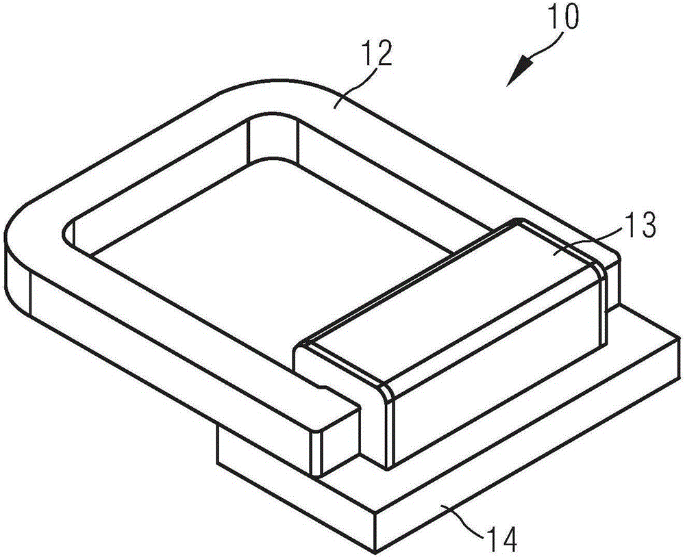
[0004] However, adding the magnetically conductive sheet 14 will cause the volume of the power supply device 10 to be too large, or under the condition that the volume of the power supply device 10 remains constant, the size of the primary side winding is limited; in addition, the iron core 12 and the magnetically conductive sheet 14 are made of different The material cost is relatively high, and different control ranges require different control circuits, resulting in a complex structure of the entire power supply device 10, which further increases the cost

Method used


Image

  • Circuit breaker, power supply device and power supply method
  • Circuit breaker, power supply device and power supply method
  • Circuit breaker, power supply device and power supply method

Examples


Embodiment Construction

[0064] In order to make the purpose, technical solution and advantages of the present invention clearer, the following examples are given to further describe the present invention in detail.

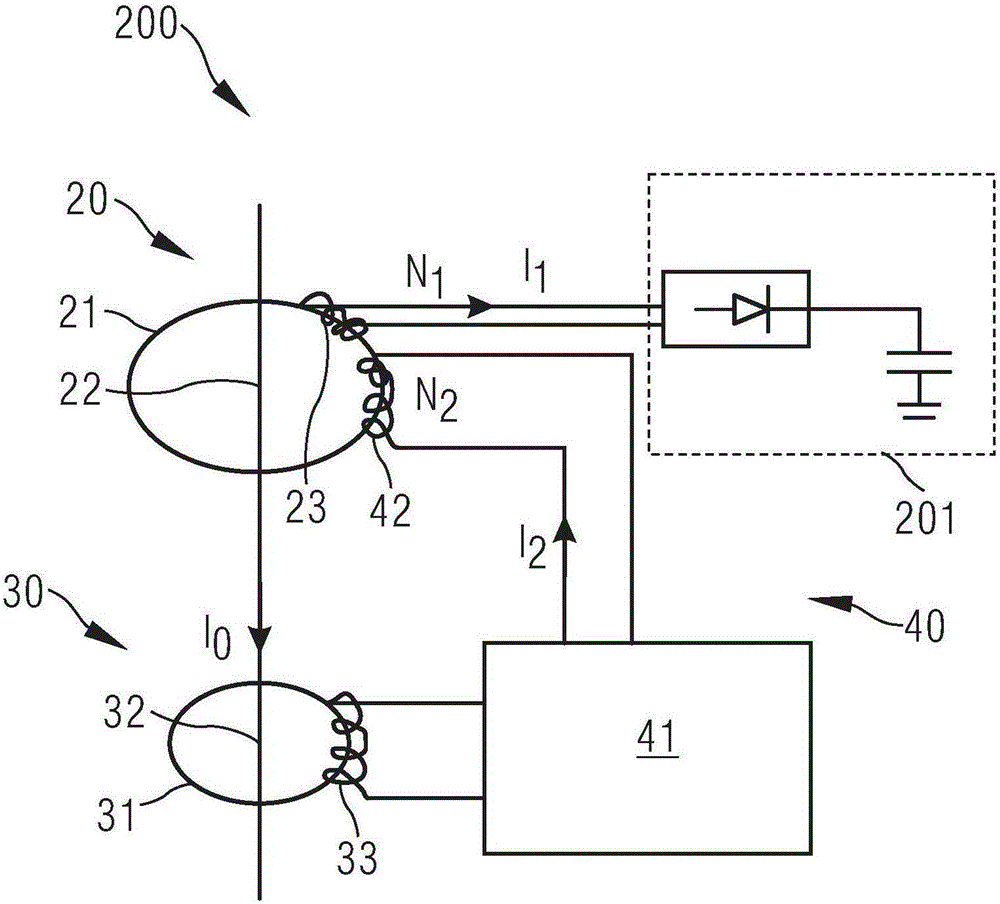
[0065] figure 2 It is a schematic structural diagram of the power supply device according to the first embodiment of the present invention. See figure 2 The power supply device 200 includes a current transformer 20 , a current sensor 30 and a control circuit 40 , the current transformer 20 includes a magnetic ring 21 and a primary winding 22 , and the primary winding 22 is wound on the magnetic ring 21 . The current sensor 30 is used to sense the current I of the primary side winding 22 0. The control circuit 40 includes a control unit 41 and a secondary winding 42, the control unit 41 is electrically connected to the current sensor 30 and the secondary winding 42, the secondary winding 42 is wound on the magnetic ring 21, and is arranged opposite to the primary winding 22 . When ...


PUM


Abstract

The invention provides a circuit breaker, a power supply device and a power supply method. The power supply device comprises a current transformer, a current sensor and a control circuit, wherein the current transformer comprises a magnetic ring and a primary-side winding, and the primary-side winding is wound on the magnetic ring; the current sensor is used for sensing current of the primary-side winding; the control circuit comprises a control unit and a secondary-side winding, the control unit is electrically connected with the current sensor and the secondary-side winding, and the secondary-side winding is wound on the magnetic ring and is arranged opposite to the primary-side winding; when the current sensor senses that a value of the current in the primary-side winding is greater than a first preset threshold or the change rate of the current in the primary-side winding is greater than a second preset threshold, the control unit controls the size of the current in the secondary-side winding. The circuit breaker, the power supply device and the power supply method are conducive to reducing the production cost and reducing the size of the power supply device, and can stabilize the power supply performance and prolong the service life of the power supply device.

Description

technical field [0001] The invention relates to the field of electric equipment, in particular to a circuit breaker, a power supply device and a power supply method. Background technique [0002] The power supply device is one of the commonly used equipment in power supply and plays a vital role in the power supply process. figure 1 It is a three-dimensional schematic diagram of a power supply device in the prior art. See figure 1 , the power supply device 10 is a current transformer, which includes an iron core 12, a primary side winding (not shown) and a secondary side winding 13, the primary side winding and the secondary side winding 13 are wound on the iron core 12, and are located on the iron core 12. Opposite side of core 12. The secondary winding 13 can supply power to electronic equipment. [0003] When the power supply device 10 is short-circuited, the magnetic flux in the iron core 12 will increase due to the excessive current change rate in the primary windin...

Claims


Application Information

Patent Timeline
Patent Type & Authority Applications(China)
IPC IPC(8): H02J5/00
Inventor 杜峰刘臻陈维刚卓越
Owner SIEMENS AG
Learn More