Sounding pipe bending phenomenon recognition method for foundation pile detection acoustic transmission method

A technology of foundation pile detection and identification method, which is applied in the direction of using sound waves/ultrasonic waves/infrasonic waves to analyze solids, etc., can solve problems such as the inability to identify the bending of acoustic measuring tubes, and achieve the effects of promoting development, ensuring project quality, and high feasibility

Inactive Publication Date: 2017-03-15
HUAZHONG UNIV OF SCI & TECH
View PDF3 Cites 6 Cited by
  • Summary
  • Abstract
  • Description
  • Claims
  • Application Information

AI Technical Summary

Problems solved by technology

[0008] In view of the above defects or improvement needs of the prior art, the present invention provides a method for identifying the bending phenomenon of the acoustic tube based on the pile detection acoustic transmission method, thereby solving the problem that the bending phenomenon of the acoustic tube cannot be identified in the prior art

Method used


Image

  • Sounding pipe bending phenomenon recognition method for foundation pile detection acoustic transmission method
  • Sounding pipe bending phenomenon recognition method for foundation pile detection acoustic transmission method
  • Sounding pipe bending phenomenon recognition method for foundation pile detection acoustic transmission method

Examples


Embodiment Construction

[0039] In order to make the object, technical solution and advantages of the present invention clearer, the present invention will be further described in detail below in conjunction with the accompanying drawings and embodiments. It should be understood that the specific embodiments described here are only used to explain the present invention, not to limit the present invention. In addition, the technical features involved in the various embodiments of the present invention described below can be combined with each other as long as they do not constitute a conflict with each other.

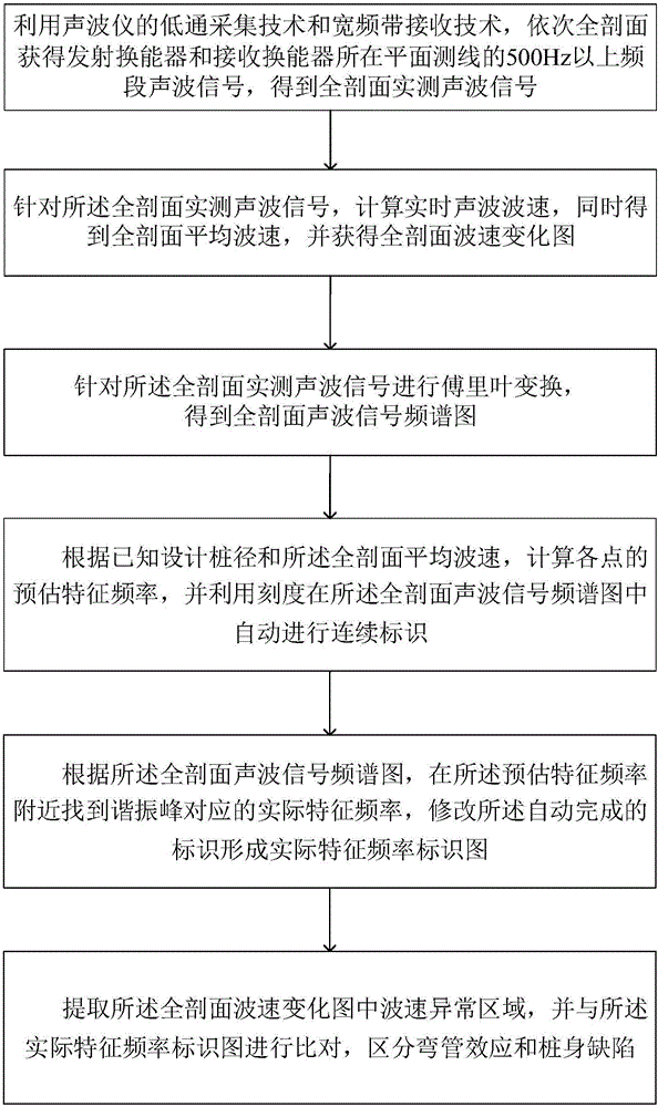
[0040] Such as figure 1 As shown, in order to solve the above problems, the embodiment of the present invention provides a method for identifying the bending phenomenon of the acoustic tube based on the pile detection acoustic transmission method. When the wave velocity at a certain measurement position is obviously abnormal from other normal wave velocity values, the calculated Measure the est...


PUM


Abstract

The invention belongs to the field of engineering measurement, and discloses a sounding pipe bending phenomenon recognition method for a foundation pile detection acoustic transmission method. The sounding pipe bending phenomenon recognition method comprises the following steps: by using a low-pass acquisition and broadband response and receiving technique, sequentially measuring real-time acoustic signals of different points of a longitudinal cross section so as to obtain a full cross section wave velocity variation diagram; performing Fourier transform on the acoustic signals so as to obtain a full cross section acoustic signal frequency domain diagram; calculating estimated characteristic frequencies of different points according to the wave velocity variation diagram and designed pile diameters; finding actual characteristic frequencies near the estimated characteristic frequencies of different points to the measured in the full cross section acoustic signal frequency domain diagram; and if the actual wave velocity of one area in the wave velocity variation diagram is remarkably deviated from a normal value, and the characteristic frequencies in the acoustic signal frequency domain diagram are still approximate to the estimated characteristic frequencies, determining that the area belongs to sounding pipe bending and is unrelated to foundation pipe quality. By adopting the sounding pipe bending phenomenon recognition method, problems which are hard to solve by using a conventional acoustic transmission method and are caused by pipe bending effects can be effectively solved, and engineering loss which can be caused by incorrect judgment and mal-judgment can be avoided.

Description

technical field [0001] The invention belongs to the field of engineering measurement, and more specifically relates to a method for identifying the bending phenomenon of an acoustic measuring tube used in the acoustic wave transmission method for foundation pile detection. Background technique [0002] During the process of ultrasonic waves passing through the concrete medium, the performance and structure of the medium itself will affect various acoustic parameters of the acoustic signal. At this stage, the acoustic parameters generally investigated in concrete quality testing include wave velocity, amplitude, frequency and waveform. [0003] Changes in the speed of sound waves: Sound waves travel at different speeds in concrete with different materials. In general, the denser the internal structure of the concrete medium, the higher the elastic modulus, and the lower the porosity, the higher the wave velocity of the sound wave and the strength of the concrete; , necking,...

Claims


Application Information

Patent Timeline
IPC IPC(8): G01N29/07
Inventor 王雪峰王淼坤刘宏华瞿为谢建伟朱田王星冯骥
Owner HUAZHONG UNIV OF SCI & TECH
Why Eureka
Try Eureka