A column-row micro-reaction channel and micro-reactor
A technology of micro-reaction channels and micro-reactions, which is applied in chemical/physical/physical-chemical reactors, chemical instruments and methods, chemical/physical/physical-chemical processes, etc., can solve problems such as insufficient fluid mixing, and achieve improved mixing degree, uniform fluid distribution, and the effect of increasing reaction yield
- Summary
- Abstract
- Description
- Claims
- Application Information
AI Technical Summary
Problems solved by technology
Method used
Image

Examples
Embodiment 1
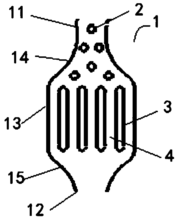
[0038] like figure 1As shown, the present invention provides a column row microreaction channel, which includes a microreaction unit 1, and the microreaction unit includes an inlet section 11, an outlet section 12 and an expansion section 13 between the two, wherein the expansion section 13, the flow cross-sectional area perpendicular to the fluid flow direction is respectively larger than the flow cross-sectional area of the inlet section 11 and the outlet section 12; and a flow area first formed between the inlet section 11 and the expansion section 13 The first curved part 14 is reduced and then enlarged, and at least one first splitter column 2 is arranged at the first curved part 14 .
[0039] In the micro-reaction channel of the column row of the present invention, a first bend portion in which the flow area first decreases and then increases is formed between the inlet section and the expansion section, and in the first bend portion At least one first splitter column...
Embodiment 2
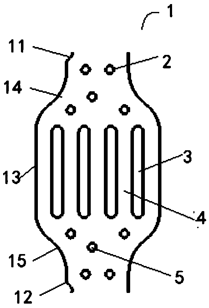
[0045] like figure 2 As shown, on the basis of Example 1, preferably, the column-row micro-reaction channel of the present invention can also be set as a reversible mixed reaction channel, that is, a communication channel is also formed between the outlet section 12 and the expansion section 13 The area of the second bend portion 15 first decreases and then increases, and a plurality of rows of second splitter columns 5 arranged along the fluid flow direction are arranged at the second bend portion 15 .
[0046] Since the fluid flow in the micro-reaction unit of Example 1 has a certain directionality, it is suitable for occasions where the flow direction is single, clear and clearly distinguishable. Once the fluid flows backward, the mixing effect will be greatly reduced. Therefore, for occasions where the flow direction is uncertain or reverse flow is required, a reversible mixing structure is required. The present invention proposes a reversible mixing structure, the flo...
Embodiment 3
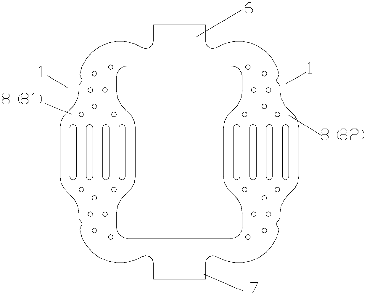
[0050] like image 3 Shown, on the basis of embodiment 1 or 2, preferably, the micro-reaction channel of the present invention also comprises " mouth " shape channel, and described " mouth " shape channel comprises inlet pipeline 6, outlet pipeline 7 and is located at two The two branch flow pipelines 8 between them, the two branch flow pipelines divide the fluid into two at the joints with the inlet pipelines, and the two branch flow pipelines and the outlet pipelines The junction combines the two fluids into one;
[0051] The micro-reaction unit is formed in the inlet pipeline 6 and / or the outlet pipeline 7 and / or at least one part of the distribution pipeline 8 .
[0052] By also including a "port"-shaped channel, and the micro-reaction unit is formed in the inlet pipeline, and / or the outlet pipeline, and / or at least one part of the split pipeline, can pass through " The “mouth”-shaped channel plays the role of diverting the fluid and converging again, increasing the suff...
PUM
 Abstract
Description
Claims
Application Information
 - Generate Ideas
- Intellectual Property
- Life Sciences
- Materials
- Tech Scout
- Unparalleled Data Quality
- Higher Quality Content
- 60% Fewer Hallucinations
Browse by: Latest US Patents, China's latest patents, Technical Efficacy Thesaurus, Application Domain, Technology Topic, Popular Technical Reports.
© 2025 PatSnap. All rights reserved.Legal|Privacy policy|Modern Slavery Act Transparency Statement|Sitemap|About US| Contact US: help@patsnap.com