
Environment-friendly life, medical and construction solid trash incinerator

An environmentally friendly technology for construction solid waste, applied in the direction of incinerators, combustion methods, combustion types, etc., can solve the problems of reducing drying effect, reducing high-temperature flue gas, and a large amount of gas, so as to improve drying effect, ensure high-temperature environment, and facilitate collection of effects

Active Publication Date: 2017-03-08
吉林省拓维环保集团股份有限公司
View PDF8 Cites 7 Cited by
  • Summary
  • Abstract
  • Description
  • Claims
  • Application Information

AI Technical Summary

Problems solved by technology

[0005] Although the above-mentioned patented technology can use high-temperature flue gas to dry wet garbage to a certain extent, it has been found through experiments that the drying effect of the above-mentioned structure is not good, and the garbage at the raking rod still has a certain amount of moisture, and these moisture-containing garbage enters the furnace body The incineration in the furnace cavity will be insufficient in the future, which will not only produce a large amount of gas, but also lead to insufficient incineration, which will reduce the amount of high-temperature flue gas, resulting in a reduction of high-temperature flue gas introduced into the garbage drying box, which will in turn which in turn reduces the drying effect
[0006] When the garbage is raked into the furnace cavity, it is piled up layer by layer on the rake-shaped grate at the bottom of the furnace cavity, and is ignited by the combustion nozzle at the grate and then burned. After actual use, it is found that the garbage accumulates on the grate There is also the phenomenon of insufficient incineration, which will not only produce a large amount of toxic fumes, poor environmental performance, but also reduce the amount of high-temperature fumes, which will in turn reduce the drying effect

Method used


Image

  • Environment-friendly life, medical and construction solid trash incinerator

Examples


Embodiment Construction

[0025] Below in conjunction with accompanying drawing and embodiment the present invention will be further described:

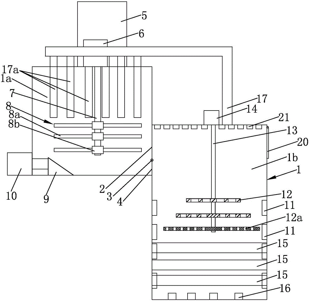
[0026] Such as figure 1 As shown, an environment-friendly living, medical and construction solid waste incinerator mainly consists of a furnace body 1, a fixed flue gas baffle 2, a movable flue gas baffle 3, a pin shaft 4, a garbage inlet pipe 5 and a motor 6, etc. constitute. Wherein, the inner wall of the furnace body 1 is covered with heat-insulating material, and the inner chamber of the furnace body is composed of an upper chamber 1a and a lower chamber 1b, wherein the upper chamber 1a and the lower chamber 1b are both rotary structures, and the upper chamber 1a The right side of the lower end directly communicates with the left side of the upper end of the lower chamber 1b. There is a metal outlet on the right side of the upper end of the lower chamber 1b, which can be completely closed by a movable heat preservation door 20, and the upper end of the ...


PUM


Abstract

The invention discloses an environment-friendly life, medical and construction solid trash incinerator. A fixed smoke baffle is vertically arranged at the connection joint of an upper cavity and a lower cavity. The upper end of the fixed smoke baffle is fixed to the inner top face of the lower cavity. A trash passing opening for trash to pass through is reserved between the lower end of the fixed smoke baffle and the bottom face of the upper cavity. A trash inlet pipe is arranged on the top of the upper cavity. A discharge port of the trash inlet pipe communicates with a feed port in the top of the upper cavity. A set of combustion spray nozzles are densely distributed on the inner wall of the lower cavity. The uppermost combustion spray nozzle is close to the lower end of the movable smoke baffle, and the lowest combustion spray nozzle is located at the bottom of the lower cavity. Gas spray nozzles are densely distributed on the inner bottom face of the lower cavity, are vertically arranged and spray gas upwards. Gas is supplied to all the gas spray nozzles by the same gas pump through external pipelines. The gas pump is arranged outside a furnace body. It is ensured that the trash incineration is sufficient, meanwhile, the effect that the trash is pre-dried through high-temperature hot gas is improved, and the environmental protection performance is good.

Description

technical field [0001] The invention relates to a garbage incinerator, in particular to an incinerator used for treating domestic, medical and construction solid waste. Background technique [0002] Garbage disposal has always been a major environmental issue of concern to the world. The existing solid waste can be mainly divided into domestic, medical and construction waste. Traditional solid waste disposal methods mainly include landfill and incineration. Landfill will occupy a lot of valuable land resources and pollute the environment at the same time, so this simple treatment method is basically no longer used. Compared with landfill treatment, waste incineration is a better treatment method. Through incineration, not only garbage The volume is greatly reduced, and at the same time, the heat generated by incineration can be used to generate electricity and heat, so as to achieve the purpose of energy reuse. [0003] Therefore, incineration technology has become a kind ...

Claims


Application Information

Patent Timeline
Patent Type & Authority Applications(China)
IPC IPC(8): F23G5/033F23G5/04F23G5/44
CPCF23G5/033F23G5/04F23G5/44F23G5/444F23G2201/10F23G2201/80
Inventor 胡兵胡飞刘福香
Owner 吉林省拓维环保集团股份有限公司
Learn More