Stable precise visual weld joint tracking system
A tracking system and sophisticated technology, applied in the field of precision visual weld seam tracking system, can solve problems such as arc light interference, complex image processing, short weld seam, etc., and achieve the effect of stable features of interest and good imaging effect
- Summary
- Abstract
- Description
- Claims
- Application Information
AI Technical Summary
Problems solved by technology
Method used
Image
Examples
Embodiment 1
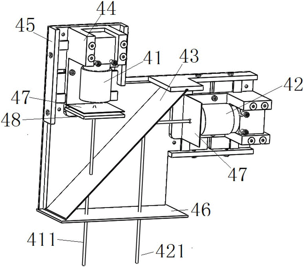
[0022] see figure 1 , which is a structural schematic diagram of a stable precision visual seam tracking system of the present invention.
[0023] Such as figure 1 , a stable and precise visual seam tracking system, comprising a welding torch 1, a controller 2, a laser 3, a dual-target imaging device 4 and a processor 5, the welding torch 1, the controller 2, a laser 3, a dual-target imaging The device 4 and the processor 5 are installed on the mobile platform 6, wherein the controller 2 and the processor 5 are not limited to be installed on the mobile platform 6, only need to ensure the connection between the controller 2 and the processor 5 and other components That's it.
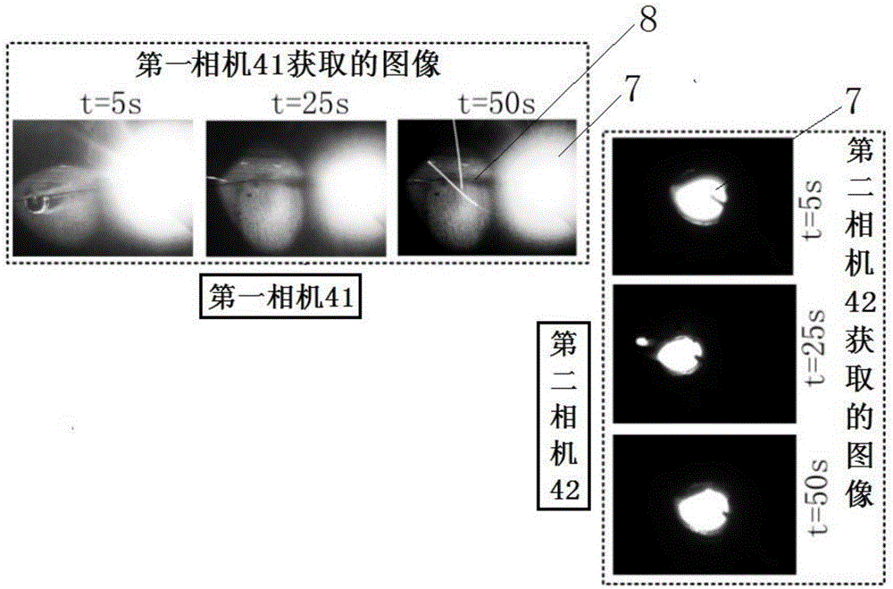
[0024] The laser 3 is used to project structured light 31 around the joint to be welded 8 connected to the front area of the molten pool 7; the dual-target imaging device 4 includes a first camera 41 and a second camera 42, the The dual-target surface imaging device 4 is used to collect image signals...
Embodiment 2
[0033] A stable precision visual seam tracking system as described above, the difference of this embodiment is that, as figure 2 As shown, a barrier lens 46 is provided at the bottom of the dual-target surface imaging device 4 to block the impact of welding slag in the welding process on the first camera 41, the second camera 42 and the semi-reflective lens 43. The damage caused, wherein, the material of the barrier lens 46 requires that the light reflected by the target to be monitored can pass through the barrier lens 46 and reach the semi-reflective lens 43, so as not to affect the imaging effect.
Embodiment 3
[0035] A stable precision visual seam tracking system as described above, the difference of this embodiment is that, as figure 2 As shown, a filter structure 47 is provided on the light transmission direction of the first camera 41 and the second camera 42, and the filter structure 47 is arranged above the semi-reflective lens 43. The optical structure 47 is used to filter out arc light interference in some wavelength bands.
[0036] Further, a light reduction structure 48 is also provided in the light transmission direction of the first camera 41 and / or the second camera 42, and the light reduction structure 48 is arranged above the semi-reflective lens 43, so The light reduction structure 48 is used to reduce light entering the first camera 41 and / or the second camera 42 to obtain a reasonable exposure. Whether it is necessary to set the light reduction structure 48 needs to be determined according to the actual situation of imaging of the first camera 41 or the second cam...
PUM
 Abstract
Description
Claims
Application Information
 - R&D
- Intellectual Property
- Life Sciences
- Materials
- Tech Scout
- Unparalleled Data Quality
- Higher Quality Content
- 60% Fewer Hallucinations
Browse by: Latest US Patents, China's latest patents, Technical Efficacy Thesaurus, Application Domain, Technology Topic, Popular Technical Reports.
© 2025 PatSnap. All rights reserved.Legal|Privacy policy|Modern Slavery Act Transparency Statement|Sitemap|About US| Contact US: help@patsnap.com


