
Assembly for a hydraulic motor-vehicle brake system and brake system having such an assembly

A braking system, a technology of motor vehicles, applied in the direction of brakes, etc.

Active Publication Date: 2017-02-22
CONTINENTAL AUTOMOTIVE TECH GMBH
View PDF6 Cites 1 Cited by
  • Summary
  • Abstract
  • Description
  • Claims
  • Application Information

AI Technical Summary

Problems solved by technology

This is the shortcoming of the previously disclosed pressure providing device
Another disadvantage of the described pressure supply device is that, when the output pressure is higher than atmospheric pressure, a standby mode in which the pump is driven but not volumetrically displaced between the first, second and third connections is not possible

Method used


Image

  • Assembly for a hydraulic motor-vehicle brake system and brake system having such an assembly
  • Assembly for a hydraulic motor-vehicle brake system and brake system having such an assembly
  • Assembly for a hydraulic motor-vehicle brake system and brake system having such an assembly

Examples


Embodiment Construction

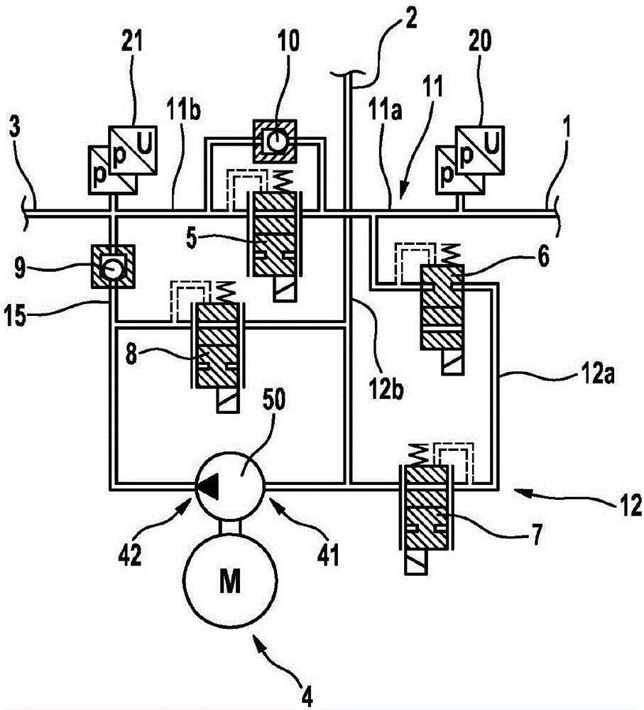
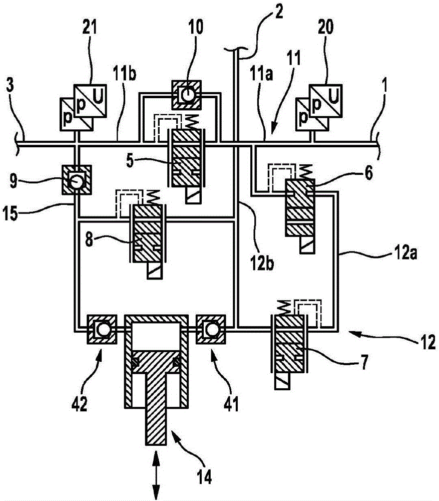
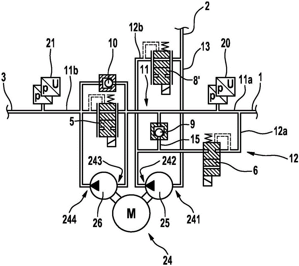
[0037] figure 1A first embodiment of an assembly according to the invention for a hydraulic motor vehicle braking system is shown in . The assembly comprises a first connection 1 for connection to the pressure chamber of the brake master cylinder, a second connection 2 for connection to a pressure medium reservoir, advantageously at atmospheric pressure, and a connection to the pressure modulation device. Output pressure connection 3. The assembly according to the example comprises a pump assembly 4 and four electrically controllable valves 5 , 6 , 7 , 8 .

[0038] A normally open and analog-controllable first valve 5 (pressure boost valve) is arranged in a hydraulic connection 11 with line sections 11 a and 11 b between first connection 1 and outlet pressure connection 3 . Connected in parallel to the first valve 5 is a non-return valve 10 which opens in the direction of the outlet pressure connection 3 .

[0039] The second valve 6 (brake master cylinder decompression rel...


PUM


Abstract

The invention relates to an assembly for a hydraulic motor-vehicle brake system, comprising: a first connection (1) for connecting to a pressure chamber of a master brake cylinder; a second connection (2) for connecting to a pressure-medium reservoir, in particular a pressure-medium reservoir under atmospheric pressure; an output pressure connection (3), in particular for connecting to a pressure modulation device; a pump assembly (4, 14, 24), which has at least a first suction side (41, 241), which is connected (12b, 13) to the second connection (2); a hydraulic connection (11) between the first connection (1) and the output pressure connection (3), in which hydraulic connection a first valve (5) is arranged, which is open when current is not applied and which can be controlled in an analog manner; and a hydraulic connection (12) between the first connection (1) and the second connection (2), in which hydraulic connection a second valve (6) is arranged, which is closed when current is not applied; wherein the first pressure side (42, 242) of the pump assembly, which is associated with the first suction side, is connected to the first suction side (41, 241) by means of a third valve (8, 8'), which is open when current is not applied and which can be controlled in an analog manner. The invention further relates to a brake system having such an assembly.

Description

technical field [0001] The invention relates to an assembly for a hydraulic motor vehicle brake system according to the preamble of claim 1 and to a brake system according to the preamble of claim 12 . Background technique [0002] From the international patent application WO 2012 / 150120 A1 a hydraulic motor vehicle braking system is known, with a dual-circuit brake master cylinder actuatable by means of a brake pedal, electrically controllable for adjusting the respective brake pressure of the wheels A pressure modulation device and an electronically controllable pressure supply device having two pumps and a normally open analog controllable valve and a normally closed analog controllable valve for each brake circuit. In this case, one of the pumps is connected on the suction side to one of the brake master cylinder pressure chambers, and the other pump is connected on the suction side to the pressure medium reservoir. The pressure sides of the pumps of a brake circuit are...

Claims


Application Information

Patent Timeline
Patent Type & Authority Applications(China)
IPC IPC(8): B60T8/40
CPCB60T8/4059B60T8/4072B60T8/3655B60T8/405B60T8/4081
Inventor S·德鲁姆M·贝西尔
Owner CONTINENTAL AUTOMOTIVE TECH GMBH
Learn More