
A high-efficiency temperature control device for handheld terminal equipment

A technology of temperature control device and handheld terminal, which is applied in the direction of cooling/ventilation/heating modification, modification through conduction heat transfer, modification with liquid cooling, etc. It can solve the problem of discounting effects, treating symptoms but not root causes, and unable to meet the needs of stable work Human perception needs and other issues, to achieve the effect of reducing the temperature of the device, solving the problem of hot equipment, and eliminating local hot spots

Active Publication Date: 2018-11-16
南京中新赛克科技有限责任公司
View PDF12 Cites 0 Cited by
  • Summary
  • Abstract
  • Description
  • Claims
  • Application Information

AI Technical Summary

Problems solved by technology

The above-mentioned methods treat the symptoms but not the root cause. Usually, they can only solve the short-term working conditions of the equipment. For example, the form of working for 5 minutes and pausing for 10 minutes cannot solve the problem of continuous heating of continuous working equipment.
It has been unable to meet the needs of modern electronic devices for stable work and good human body perception. In addition, for multi-heat source terminal equipment, the application of ultra-thin heat pipes is also greatly reduced due to the influence of space layout and heat transfer capacity.
Therefore, there is no effective solution to the hand-held terminal equipment hot problem in the industry. It is necessary to research and develop new efficient heat dissipation and temperature equalization technologies to meet the requirements of local handheld terminal equipment heat dissipation and human body perception of external surface temperature.

Method used


Image

  • A high-efficiency temperature control device for handheld terminal equipment
  • A high-efficiency temperature control device for handheld terminal equipment
  • A high-efficiency temperature control device for handheld terminal equipment

Examples


Embodiment 1

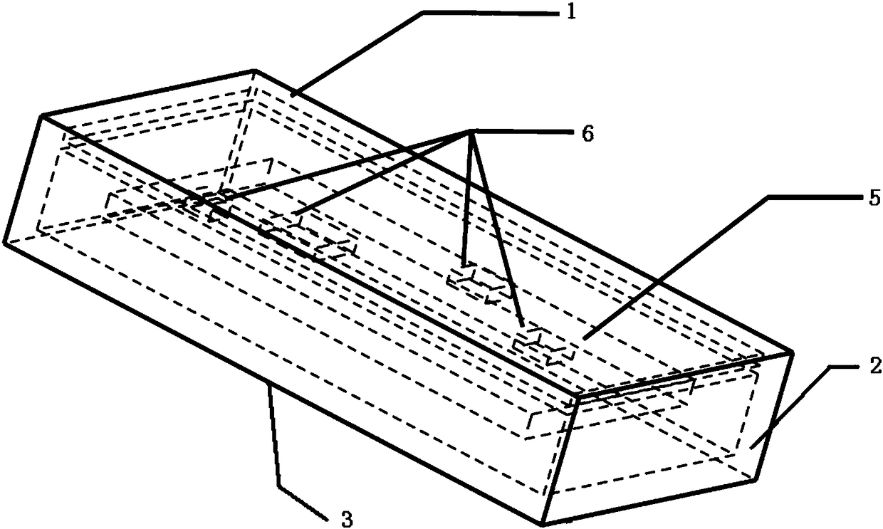
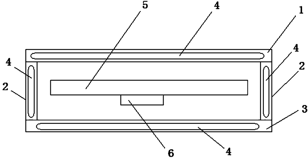
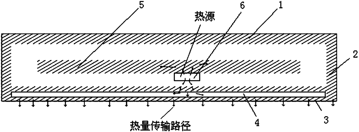
[0022] Such as Figure 1-3 As shown, a high-efficiency temperature control device for handheld terminal equipment includes an upper structural plate 1, a middle connecting plate 2, a lower structural plate 3 and a single plate 5, and the upper structural plate 1 and the lower structural plate 3 are connected by four middle parts. The plates 2 are connected to form a cavity structure, and the veneer 5 is arranged in the cavity between the upper structural plate 1 and the lower structural plate 3. The single plate 5 is provided with a heating chip 6, and the lower structural plate 3 and the middle connecting plate 2 are both It is a cavity structure, and a phase change material 4 is arranged in the cavity; the upper structural plate 1, the middle connecting plate 2 and the lower structural plate 3 are made of metal; the phase change material 4 is an organic phase change material.

[0023] The high-efficiency temperature control device of the handheld terminal device of the prese...

Embodiment 2

[0027] It is basically the same as Embodiment 1, except that: the heating chip 6 is arranged on the veneer 5 facing the upper structural plate 1, the upper structural plate 1 is a cavity structure, and a phase change material 4 is arranged in the cavity; the upper structure The plate 1 and the lower structural plate 3 are made of heat-conducting plastic; the phase change material 4 is an inorganic phase change material.

[0028] When the heating chip 6 faces the upper structure plate 1 , the phase change material 4 can be filled in the upper structure, and heat can be absorbed through the phase change material 4 in the cavity of the upper structure plate 1 .

Embodiment 3

[0030] Such as figure 2 As shown, it is basically the same as Embodiment 1, except that the heating chip 6 is arranged on the single board 5 facing the upper structural plate 1, and the upper structural plate 1, the middle connecting plate 2 and the lower structural plate 3 are all cavities. structure, the cavity is equipped with a phase change material 4; the phase change material 4 is a phase change material mixed with an organic phase change material and an inorganic phase change material.

[0031] Usually, the heating chip 6 of the inner single board 5 faces the lower structural board 3 , so the lower structural board 3 is filled with phase change material 4 . If the heating chip 6 faces the upper structural plate 1, the phase change material 4 can be filled in the upper structural plate 1, the middle connecting plate 2 and the lower structural plate 3 at the same time. The variable material 4 absorbs heat simultaneously.

[0032] In the phase change energy storage solu...


PUM


Abstract

The invention discloses an efficient temperature control device for a handheld terminal device. The device comprises an upper structural plate, middle connection plates, a lower structural plate and a single board. The periphery of the upper structural plate and the periphery of the lower structural plate are connected to form a cavity structure through the four middle connection plates, the single board is arranged in the cavity between the upper structural plate and the lower structural plate, the single board is provided with a heating chip, the lower structural plate is of a cavity structure, and a phase change material is arranged in the cavity. The temperature of the outer surface of equipment and the temperature of the inner chip can be effectively controlled, characteristics of the phase change material are effectively used, and precise control over the temperature of the outer surface is implemented; the temperature of the single board and the device can be reduced, the temperature of the outer surface of the equipment can be reduced, so the temperature of the outer surface is made uniform, and the problem that the equipment is hot is solved; local hotspots possibly generated by multiple local high-heat-density hot source points can be effectively eliminated, temperature uniformity of a heated face is improved, the surface temperate level of the electronic equipment is lowered, and accordingly safe, stable and efficient work of an electronic equipment system is guaranteed.

Description

technical field [0001] The invention relates to a high-efficiency temperature control device for handheld terminal equipment. Background technique [0002] With the continuous development of electronic technology, the power of electronic equipment systems is getting larger and smaller, but the physical size is getting smaller and smaller, and the heat flux is also increasing sharply. If the waste heat cannot be discharged in time, the system temperature will rise accordingly. Studies have shown that for every 10°C increase in the temperature of electronic equipment systems, the failure rate increases by more than 50%. Therefore, how to discharge the waste heat of electronic equipment systems is very important to improve their reliability. In an electronic equipment system, the reliability of a single electronic component or circuit depends on the operating temperature, and a good environment must be provided for the electronic components so that the operating temperature do...

Claims


Application Information

Patent Timeline
Patent Type & Authority Patents(China)
IPC IPC(8): H05K7/20
CPCH05K7/2029H05K7/20518
Inventor 朱旺法胡海聿
Owner 南京中新赛克科技有限责任公司
Learn More