Efficient temperature control device for handheld terminal device
A technology of temperature control device and handheld terminal, which is applied in the direction of modification using liquid cooling, modification through conduction heat transfer, cooling/ventilation/heating modification, etc., which can solve the needs of human body perception, effect discount, Solve the symptoms but not the root cause, and achieve the effect of eliminating local hot spots, reducing the temperature of the device, and solving the problem of hot equipment
- Summary
- Abstract
- Description
- Claims
- Application Information
AI Technical Summary
Problems solved by technology
Method used
Image
Examples
Embodiment 1
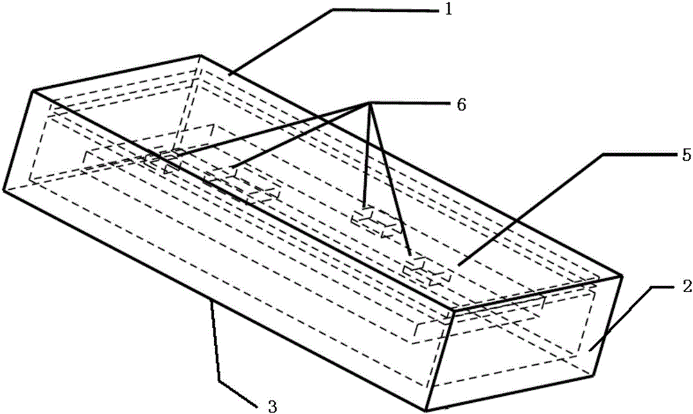
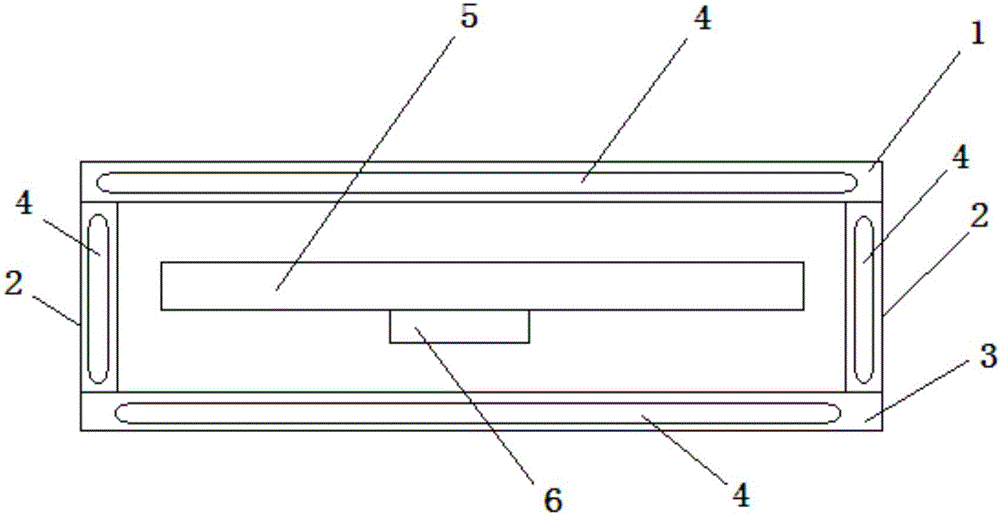
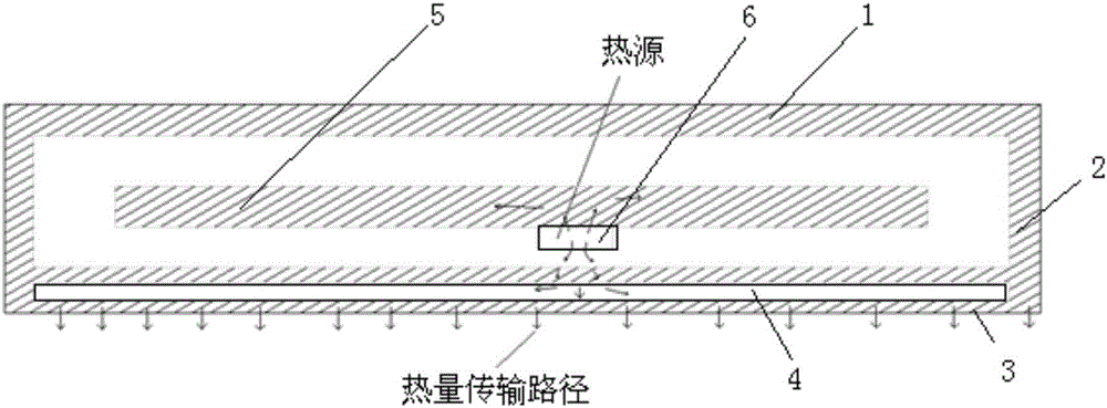
[0022] Such as Figure 1-3 As shown, a high-efficiency temperature control device for handheld terminal equipment includes an upper structural plate 1, a middle connecting plate 2, a lower structural plate 3 and a single plate 5, and the upper structural plate 1 and the lower structural plate 3 are connected by four middle parts. The plates 2 are connected to form a cavity structure, and the veneer 5 is arranged in the cavity between the upper structural plate 1 and the lower structural plate 3. The single plate 5 is provided with a heating chip 6, and the lower structural plate 3 and the middle connecting plate 2 are both It is a cavity structure, and a phase change material 4 is arranged in the cavity; the upper structural plate 1, the middle connecting plate 2 and the lower structural plate 3 are made of metal; the phase change material 4 is an organic phase change material.
[0023] The high-efficiency temperature control device of the handheld terminal device of the prese...
Embodiment 2
[0027] It is basically the same as Embodiment 1, except that: the heating chip 6 is arranged on the single board 5 facing the upper structural plate 1, the upper structural plate 1 is a cavity structure, and a phase change material 4 is arranged in the cavity; the upper structure The plate 1 and the lower structural plate 3 are made of heat-conducting plastic; the phase change material 4 is an inorganic phase change material.
[0028] When the heating chip 6 faces the upper structure plate 1 , the phase change material 4 can be filled in the upper structure, and heat can be absorbed through the phase change material 4 in the cavity of the upper structure plate 1 .
Embodiment 3
[0030] Such as figure 2 As shown, it is basically the same as Embodiment 1, except that the heating chip 6 is arranged on the single board 5 facing the upper structural plate 1, and the upper structural plate 1, the middle connecting plate 2 and the lower structural plate 3 are all cavities. structure, the cavity is equipped with a phase change material 4; the phase change material 4 is a phase change material mixed with an organic phase change material and an inorganic phase change material.
[0031] Usually, the heating chips 6 of the inner single board 5 face the lower structural board 3 , so the lower structural board 3 is filled with phase change materials 4 . If the heating chip 6 faces the upper structural plate 1, the phase change material 4 can be filled in the upper structural plate 1, the middle connecting plate 2 and the lower structural plate 3 at the same time. The variable material 4 absorbs heat simultaneously.
[0032] In the phase change energy storage sol...
PUM
 Abstract
Description
Claims
Application Information
 - R&D
- Intellectual Property
- Life Sciences
- Materials
- Tech Scout
- Unparalleled Data Quality
- Higher Quality Content
- 60% Fewer Hallucinations
Browse by: Latest US Patents, China's latest patents, Technical Efficacy Thesaurus, Application Domain, Technology Topic, Popular Technical Reports.
© 2025 PatSnap. All rights reserved.Legal|Privacy policy|Modern Slavery Act Transparency Statement|Sitemap|About US| Contact US: help@patsnap.com


