
Power tool and control method for same

A technology of power tools and drive control circuits, which is applied in the direction of electrical program control, sequence/logic controller program control, etc., and can solve the problems of high manufacturing cost, complex structure, and inconvenient fixing.

Active Publication Date: 2017-02-22
POSITEC POWER TOOLS (SUZHOU) CO LTD
View PDF5 Cites 1 Cited by
  • Summary
  • Abstract
  • Description
  • Claims
  • Application Information

AI Technical Summary

Problems solved by technology

[0003] Chainsaw is one of the commonly used power tools. Usually, during the cutting process, the user cannot accurately control the cutting length, and overcutting is prone to occur
Therefore, electric saws for real-time measurement and display of cutting parameters such as cutting length have appeared on the market. However, users still need to pay attention to the position of the saw blade and accessories for displaying cutting parameters, which is inconvenient to use.
In order to solve the above problems, there is also a chainsaw that adopts a mechanical stop method. For example, the patent application No. 201280055535.8 is equipped with a separate accessory, which uses a mechanical stop method to prevent the machine from pushing forward, but the structure is complicated and inconvenient. Fixed and expensive to manufacture

Method used


Image

  • Power tool and control method for same
  • Power tool and control method for same
  • Power tool and control method for same

Examples


Embodiment Construction

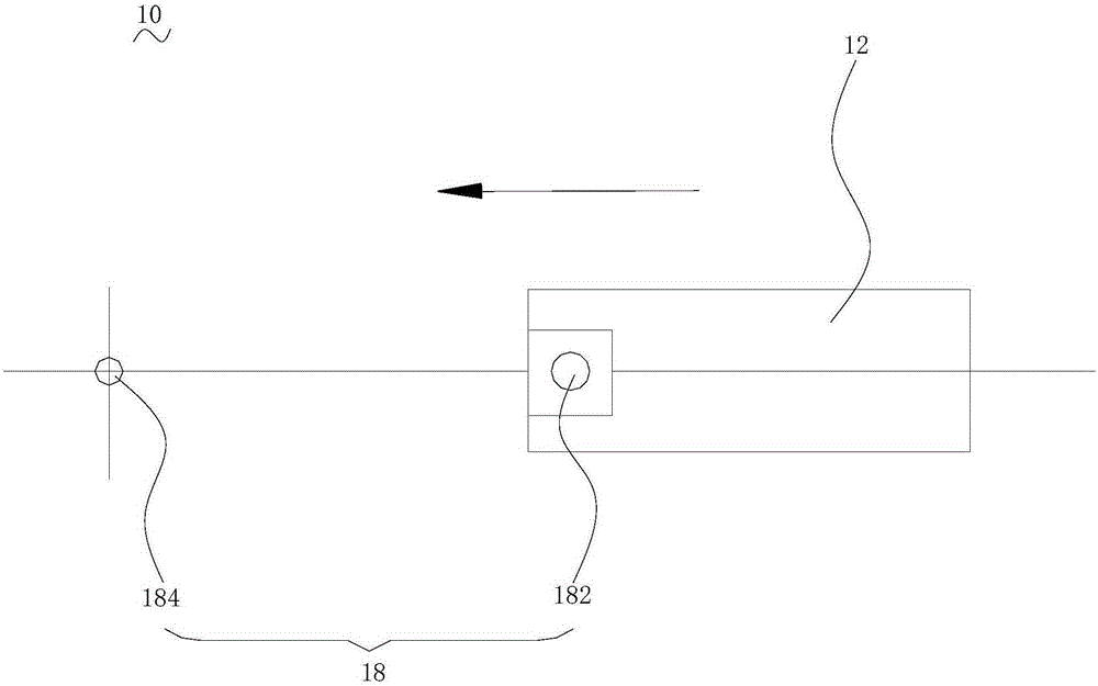
[0032] In order to facilitate the understanding of the present invention, the present invention will be described more fully below with reference to the associated drawings. Preferred embodiments of the invention are shown in the accompanying drawings. However, the present invention can be embodied in many different forms and is not limited to the embodiments described herein. On the contrary, these embodiments are provided to make the understanding of the disclosure of the present invention more thorough and comprehensive.

[0033] It should be noted that when an element is referred to as being “fixed” to another element, it can be directly on the other element or there can also be an intervening element. When an element is referred to as being "connected to" another element, it can be directly connected to the other element or intervening elements may also be present. The terms "vertical," "horizontal," "left," "right," and similar expressions are used herein for purposes ...


PUM


Abstract

The invention relates to a power tool which comprises a power tool body. The power tool body comprises a housing, a motor, an working head, a power supply, a detecting unit and a control unit. The motor is accommodated in the housing. The working head is driven by the motor and a power is output from the motor. The power supply supplies power to the motor. The detecting unit is used for determining whether the power tool body arrives at a preset position of a workpiece. The control unit is connected with the detecting unit and the motor. On the condition that the detecting unit detects a fact that the power tool body reaches the preset position of the workpiece, the motor is stopped so that the working head correspondingly stops power outputting to a position with the anticipated cutting length on the workpiece. Therefore, an operator does not require paying attention to the accurate position of a saw blade, thereby preventing excessive cutting. Furthermore automatic stopping is realized, thereby reducing operation difficulty of the user and realizing high convenience in use. Furthermore, compared with a mechanical backstop mode, the power tool has advantages of no requirement for individual arrangement of a blocking fitting, simple structure and low manufacture cost. The invention further provides a control method for the power tool.

Description

technical field [0001] The invention relates to a power tool and a control method for the power tool. Background technique [0002] In recent years, with the development of domestic urban construction, urban greening has formed a larger industry, and the urban maintenance of urban greening relies on gardening tools to achieve. [0003] A chainsaw is one of the commonly used power tools. Usually, during the cutting process, the user cannot accurately control the cutting length, and overcutting is prone to occur. Therefore, electric saws for real-time measurement and display of cutting parameters such as cutting length have appeared on the market. However, users still need to pay attention to the position of the saw blade and accessories for displaying cutting parameters, which is inconvenient to use. In order to solve the above problems, there is also a chainsaw that adopts a mechanical stop method. For example, the patent application No. 201280055535.8 is equipped with a se...

Claims


Application Information

Patent Timeline
IPC IPC(8): G05B19/04
CPCG05B19/04
Inventor 黄文进
Owner POSITEC POWER TOOLS (SUZHOU) CO LTD
Learn More