Terahertz near-field imaging system and terahertz near-field imaging method
A terahertz near-field and imaging system technology, which is applied in the field of optical applications, can solve the problems of complex THz structure, harsh detector requirements, and low THz output power, and achieve the effects of simple structure, improved defects, and high precision
- Summary
- Abstract
- Description
- Claims
- Application Information
AI Technical Summary
Problems solved by technology
Method used
Image
Examples
Embodiment 1
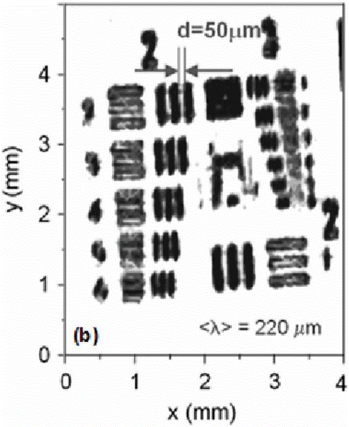
[0043] The present invention provides a terahertz near-field imaging system, please refer to image 3 , which is a schematic structural diagram of the terahertz near-field imaging system, including a terahertz coherent light source module 1, an external cavity optical path module 2, and a near-field probe module 3; wherein: the terahertz coherent light source module 1 includes a terahertz light source 101 And the lock-in amplifier 102 connected with the terahertz light source 101; the external cavity optical path module 2 includes a first off-axis parabolic mirror 201 and a second off-axis parabolic mirror 202; the near-field probe module 3 includes a near-field Probe 301.
[0044] Specifically, the terahertz light source 101 is used to generate a terahertz signal and receive the reflection signal of the near-field terahertz signal of the sample 4 to generate a self-mixing effect in the resonant cavity of the terahertz light source 101 . In this embodiment, the terahertz cohe...
Embodiment 2
[0062] The present invention also provides a terahertz near-field imaging method, the method comprising: transmitting the reflection signal of the near-field terahertz signal of the sample to the light-emitting end face of the terahertz light source, and generating a self-mixing effect in the resonant cavity of the terahertz light source , and the signal extraction of the imaging sampling position is realized by detecting the self-mixing signal of the terahertz light source.
[0063] As an example, the terahertz light source may choose any terahertz wave generating device with a resonant cavity. In this embodiment, the terahertz light source is preferably a terahertz quantum cascade laser, which can generate high-power terahertz radiation, which is beneficial for signal detection.
[0064] As an example, the detection self-mixing signal selects the voltage signal or current signal of the terahertz light source, and selects the peak value within one modulation period as the res...
Embodiment 3
[0071] This embodiment provides a method for constructing a terahertz near-field imaging system, including the following steps:
[0072] Step 1: Construct a near-field imaging optical path system.
[0073] 1) Place the first off-axis parabolic mirror (hereinafter referred to as PM1) and the second off-axis parabolic mirror (hereinafter referred to as PM2) in the optical path of the external cavity on parallel optical tracks to facilitate the subsequent adjustment of the length of the external cavity;
[0074] 2) Place the visible light source at the focal point of PM1 for optical path calibration and sample position calibration, adjust the pitch angles of PM1 and PM2 according to the visible light mark, so that the converging spot of PM2 is at the same height as the visible light source, and the position of the spot coincides with the focal position of PM2. The light spot changes along the direction of the optical axis to present a uniform circular zoom;
[0075] 3) Determine...
PUM
| Property | Measurement | Unit |
|---|---|---|
| angle of incidence | aaaaa | aaaaa |
Abstract
Description
Claims
Application Information
 - Generate Ideas
- Intellectual Property
- Life Sciences
- Materials
- Tech Scout
- Unparalleled Data Quality
- Higher Quality Content
- 60% Fewer Hallucinations
Browse by: Latest US Patents, China's latest patents, Technical Efficacy Thesaurus, Application Domain, Technology Topic, Popular Technical Reports.
© 2025 PatSnap. All rights reserved.Legal|Privacy policy|Modern Slavery Act Transparency Statement|Sitemap|About US| Contact US: help@patsnap.com


