
Comprehensive performance resting experiment table for precision speed reduction device

A comprehensive performance testing, precision reducer technology, applied in the testing of machine/structural components, machine gear/transmission mechanism testing, mechanical component testing, etc. Stiffness and transmission efficiency, inability to test the transmission efficiency of the reducer, etc., to meet the requirements of high-precision performance testing and testing, improve testing efficiency, and improve testing stability.

Inactive Publication Date: 2017-02-22
CENT SOUTH UNIV
View PDF8 Cites 52 Cited by
  • Summary
  • Abstract
  • Description
  • Claims
  • Application Information

AI Technical Summary

Problems solved by technology

This method uses the load arm to add load to the output end of the tested reducer, and uses the servo motor to load the input end of the tested reducer. According to the patent description, this system cannot test the transmission efficiency of the reducer under the specified load, and cannot test the specified The torsional rigidity at one angle point cannot test the performance of various types of precision reducers, and the torsional rigidity and transmission efficiency cannot be tested on the same device, and the torsional rigidity test range is small, the test efficiency is low, and it is inconvenient to install and disassemble.

Method used


Image

  • Comprehensive performance resting experiment table for precision speed reduction device
  • Comprehensive performance resting experiment table for precision speed reduction device
  • Comprehensive performance resting experiment table for precision speed reduction device

Examples


Embodiment Construction

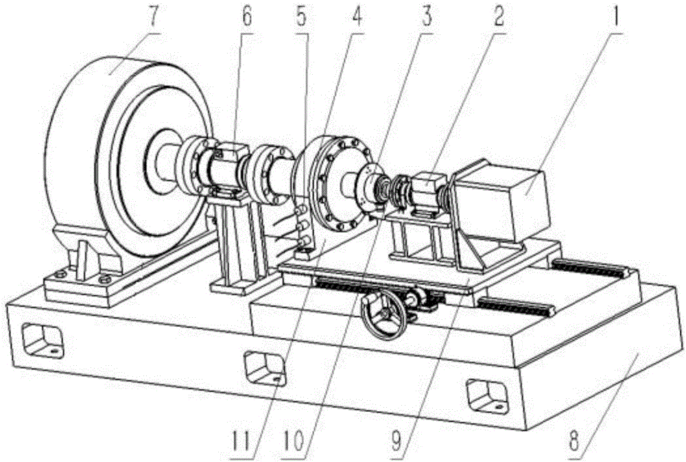
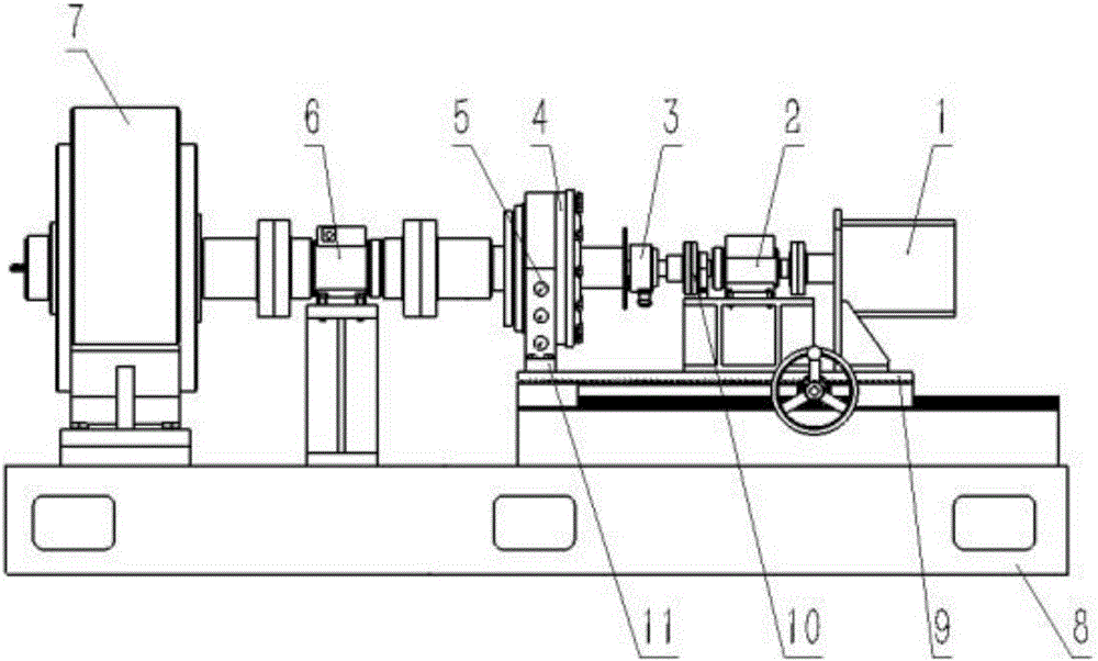
[0028] The specific implementation of the present invention will be further described below in conjunction with the accompanying drawings.

[0029] Such as figure 1 , figure 2 , image 3 As shown, the precision reducer comprehensive performance test bench provided by the present invention consists of a servo motor 1, an input torque speed sensor 2, a high-precision encoder 3, a measured reducer 4, a vibration noise and temperature sensor 5, an output terminal The torque speed sensor 6, the main parts of the magnetic powder brake 7 and the base 8, the horizontal slide table 9, the coupling 10, the reducer mounting seat 11 and other connected and fixed auxiliary parts are characterized in that: the servo motor 1 is input The end torque torque sensor 2 is connected to the input shaft of the tested reducer 4, the high-precision encoder 3 is installed on the input shaft of the tested reducer 4, and the high-precision encoder 3 is used to read the input of the tested reducer 4 T...


PUM


Abstract

The invention discloses a comprehensive performance resting experiment table for a precision speed reduction device. The comprehensive performance resting experiment table comprises main components, such as a servo motor, an input end torque and rotational speed sensor, a high precision encoder, a measured speed reducer, a vibration noise and temperature sensor, an output torque and rotational speed sensor, a magnetic powder brake, and auxiliary components for connecting and fixing, such as a base, a horizontal sliding table, a coupling and a speed reducing mounting base; the comprehensive performance resting experiment table adopts the mode that the magnetic powder brake provides input end load, the input end of the servo motor is loaded, and angle, rotate speed, temperature, vibration and noise testing devices are added in the middle, so as to test the comprehensive performances of the precision speed reduction device. The comprehensive performance resting experiment table can accomplish testing of performances, such as transmission efficiency, torsional rigidity, vibration, noise and temperature rise, on one experiment table, and can test the comprehensive performances of different models of precision speed reduction devices. The comprehensive performance resting experiment table has the advantages of simple structure, high testing precision and high automation degree, and can meet the testing and detection requirements on the comprehensive performances of the precision speed reduction device.

Description

technical field [0001] The invention relates to the technical field of comprehensive performance testing of precision reducers, in particular to an experimental platform for comprehensive performance testing of precision reducers for joints of industrial robots. Background technique [0002] With the arrival of my country's aging population and rising labor costs, industrial robots are more and more widely used in industrial production, especially in the automotive industry. At present, common industrial robots include welding robots, palletizing robots, assembly robots, etc. As a precision reducer for industrial robot joint parts, its comprehensive performance has an extremely important impact on the product quality of industrial robots. [0003] The comprehensive performance of the precision reducer mainly includes indicators such as backlash, transmission efficiency, noise, vibration, and temperature rise. The hysteresis refers to the phenomenon that the output shaft la...

Claims


Application Information

Patent Timeline
IPC IPC(8): G01M13/02
CPCG01M13/02G01M13/025
Inventor 赵海鸣李豪武聂帅
Owner CENT SOUTH UNIV
Learn More