
Shock isolation support with servo shock isolation system

A technology of shock-isolation support and shock-isolation system, which is applied in the direction of shockproof, building components, buildings, etc., can solve the problems that the working frequency cannot be changed, cannot meet the requirements of shock isolation, and the effect of shock isolation is weakened, so as to achieve difficult resonance and simple structure , mechanical and electromechanical performance stabilization effect

Inactive Publication Date: 2017-02-22
江苏路博减振技术有限公司
View PDF7 Cites 4 Cited by
  • Summary
  • Abstract
  • Description
  • Claims
  • Application Information

AI Technical Summary

Problems solved by technology

However, for the traditional seismic isolation system, after the system is designed and manufactured, its performance is not easy to change. At the same time, as time goes by, the seismic isolation effect of the traditional seismic isolation system also weakens to a certain extent.
Moreover, the effective frequency band of the traditional isolation system is narrow, and the operating frequency cannot be changed once it is set.
Due to the uncertainty of earthquakes, traditional seismic isolation systems cannot meet the high-standard seismic isolation requirements of engineering structures, mechanical equipment, precious objects such as artworks and cultural relics with special seismic isolation requirements

Method used


Image

  • Shock isolation support with servo shock isolation system
  • Shock isolation support with servo shock isolation system

Examples


Embodiment Construction

[0013] The present invention will now be further described in conjunction with the accompanying drawings and preferred embodiments. These drawings are all simplified schematic diagrams, which only illustrate the basic structure of the present invention in a schematic manner, so they only show the configurations related to the present invention.

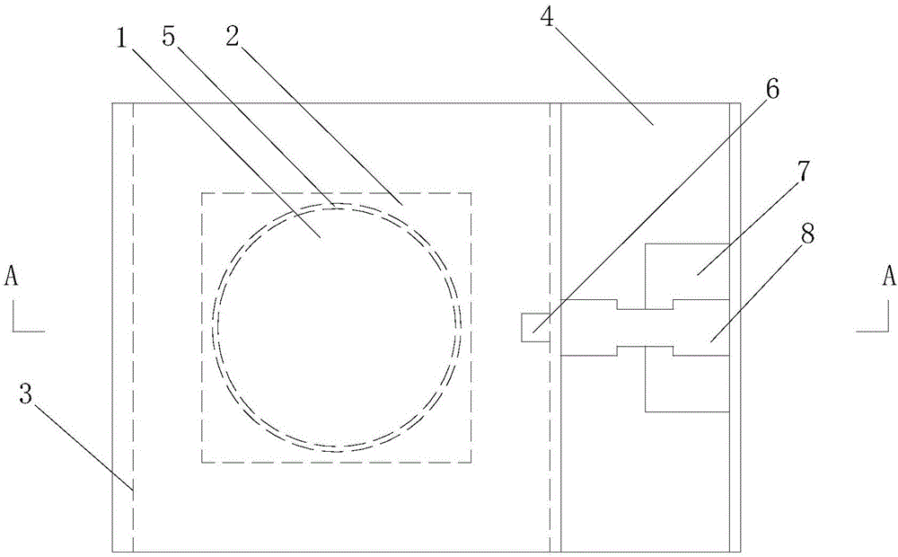
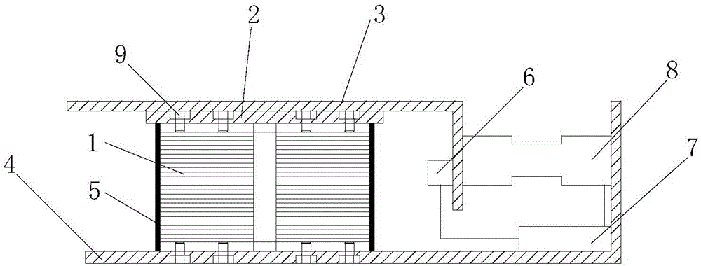
[0014] Such as Figure 1-2 A vibration isolation bearing with a servo vibration isolation system shown includes a laminated rubber bearing 1, the outer surface of the laminated rubber bearing 1 is covered with a bearing protective sleeve 5, and the upper and lower sides of the laminated rubber bearing 1 The upper flange plate 2 and the lower flange plate 4 are respectively connected by connecting bolts 9; the upper surface of the upper flange plate 2 is fixedly connected with the upper cover plate 3, and the lower flange plate 4 is installed with a A servo control system for self-adaptive adjustment of the shock-isolation bearing.

...


PUM


Abstract

The invention relates to the technical field of civil engineering, in particular to a shock isolation support with a servo shock isolation system. The shock isolation support with the servo shock isolation system comprises a laminated rubber support, wherein a support protective sleeve is arranged on the outer surface of the laminated rubber support in a sleeving manner; an upper flange plate is connected to the upper end of the laminated rubber support through connecting bolts, and a lower flange plate is connected to the lower end of the laminated rubber support through connecting bolts; an upper cover plate is fixedly connected to the upper surface of the upper flange plate; and a servo control system for enabling the shock isolation support with the servo shock isolation system to perform adaptive adjustment is mounted on the lower flange plate. The shock isolation support with the servo shock isolation system disclosed by the invention is simple in structure; a feedback control technology is introduced, so that the driving optimal feedback control of the shock isolation system is realized; the shock isolation support has an adaptive adjustment mechanism, so that different control targets can be realized; and the shock isolation support has an effective frequency bandwidth and an advantage of being not liable to resonate with a control structure, the mechanical stability and the electromechanical performance stability of the system can be realized, and the shock insulation requirements of engineering structures having special shock insulation requirements, mechanical equipment, valuable articles and the like can be met by the shock isolation support.

Description

technical field [0001] The invention relates to the technical field of civil engineering, in particular to a shock-isolation support with a servo shock-isolation system. Background technique [0002] In recent years, seismic isolation bearings can effectively isolate or reduce the input of vibration energy of earthquake ground motion to the upper structure, and can ensure the safety and use function of the upper structure in earthquakes. In the seismic isolation of buildings, bridges, precious objects, etc. Has a wide range of applications. However, for the traditional seismic isolation system, after the system is designed and manufactured, its performance is not easy to change. At the same time, as time goes by, the isolation effect of the traditional seismic isolation system also weakens to a certain extent. Moreover, the effective frequency band of the traditional seismic isolation system is narrow, and the operating frequency cannot be changed once it is set. Due to th...

Claims


Application Information

Patent Timeline
Patent Type & Authority Applications(China)
IPC IPC(8): E01D19/04E04B1/36E04H9/02E04B1/98
CPCE01D19/048E04B1/36E04H9/021
Inventor 施卫星贺礼沈阳
Owner 江苏路博减振技术有限公司
Learn More