Workpiece surface laser shocking process utilizing surface micro textures for removing residual stress holes

A technology of workpiece surface and residual stress, which is applied to the improvement of process efficiency, manufacturing tools, heat treatment equipment, etc., can solve the problems of high processing cost, reduced service life, and lack of compressive stress in the center of the spot, so as to reduce processing cost and eliminate residual stress Hole, the effect of improving processing efficiency

Active Publication Date: 2017-02-22
NANTONG UNIVERSITY
View PDF10 Cites 10 Cited by
  • Summary
  • Abstract
  • Description
  • Claims
  • Application Information

AI Technical Summary

Problems solved by technology

The appearance of the phenomenon of "residual stress hole" leads to the loss of compressive stress in the center of the laser shock strengthening spot, and even the formation of tensile stress, which makes the spot form a large stress gradient. In actual production and application, it is very easy to cause workpieces after laser shock strengthening. Cracks occur, seriously reducing life
[0005] Changing the Gauss circular spot to a uniform square spot by the "optical binary diffraction" method can effectively suppress the formation of "residual stress holes" and form a relatively uniform residual compressive stress layer, but the maximum residual compressive stress value of the surface formed by the square spot and The depth of the plastic-affected layer will be reduced to a certain extent, and the processing cost is high

Method used


Image

  • Workpiece surface laser shocking process utilizing surface micro textures for removing residual stress holes
  • Workpiece surface laser shocking process utilizing surface micro textures for removing residual stress holes
  • Workpiece surface laser shocking process utilizing surface micro textures for removing residual stress holes

Examples


Embodiment Construction

[0034] The present invention will be further described below in conjunction with the accompanying drawings and specific embodiments.

[0035] In this embodiment, a laser shock process on the surface of a workpiece using surface micro-texture to remove residual stress holes is characterized in that the steps are as follows:

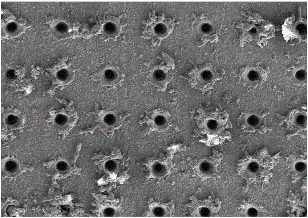
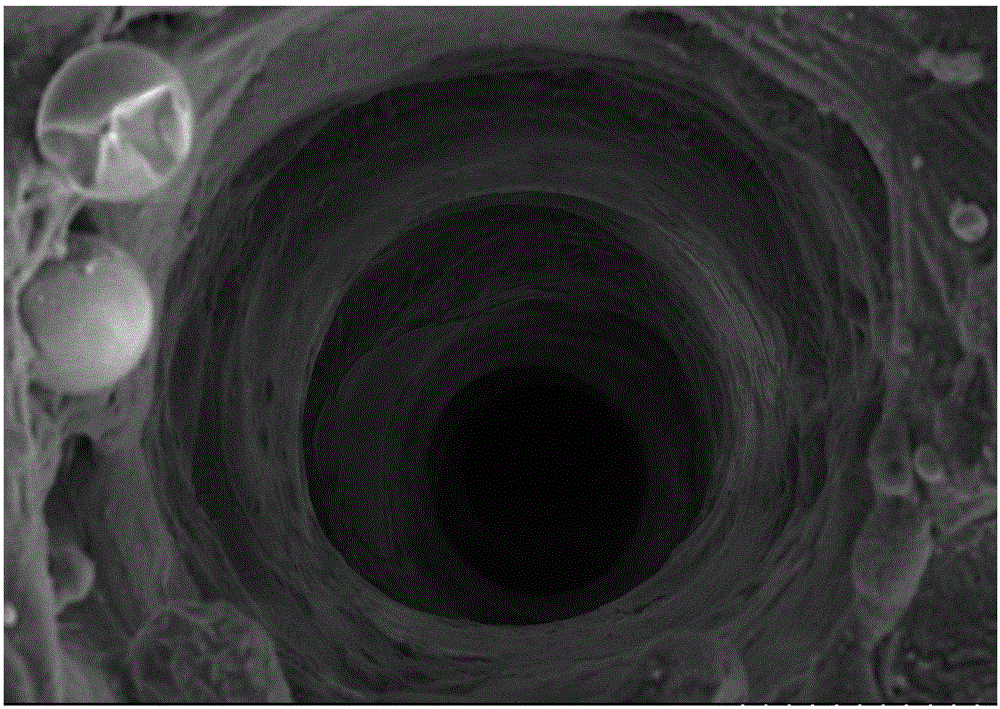
[0036] Step 1. Perform laser micro-texture treatment on the surface of the workpiece (the surface of the workpiece is pre-polished into a mirror surface) (here, the thermal effect of the laser is used for processing, using a fiber laser and a weak laser), the impact laser energy is P0, and the micro-texture density is B, The range of shock laser energy P0 is P1-P2. Preferably, the energy P0 of the shock laser is in the range of 0.2 mj-1 mj, the spot size of the shock laser is 1 μm, and the distance between the micro-texture pits is in the range of 0-140 μm. In this example, the 7050 aluminum alloy material was selected, and the laser with a single pulse e...


PUM

PropertyMeasurementUnit
sizeaaaaaaaaaa

Abstract

The invention relates to a workpiece surface laser shocking process utilizing surface micro textures for removing residual stress holes. Micro texture laser parameters are optimized, the purpose of releasing residual stress is achieved through array micropores formed by the laser micro textures, and meanwhile, the micropores formed by the micro textures play a role in blocking in the rarefaction wave transmitting process, surface converged waves cannot arrive at a light spot center, the residual stress holes cannot be formed, and a PDVF piezoelectric sensor is used for carrying out monitoring on the workpiece surface to ensure that rarefaction waves cannot be converged towards the light spot center. In addition, the laser parameter of laser shocking peening is converted into a laser parameter of deionized water serving as a restraint layer, and therefore the process can be applied to the industry on a large scale. The process is used for carrying out laser shocking peening treatment on the workpiece surface, the residual stress holes can be directly removed without changing the light spot shape and without a high overlap rate, and the machining cost is reduced while the machining efficiency is improved.

Description

technical field [0001] The invention relates to a laser shock process on the surface of a workpiece for removing residual stress holes by using surface micro-texture, and belongs to the technical field of laser processing. Background technique [0002] Laser Shocking Peening (LSP) technology, also known as laser peening technology. Laser shock peening is the use of high power density (GW / cm 2 level), short pulse (10-30ns level) laser irradiates the energy absorbing layer coated on the metal surface through the confinement layer, the coating absorbs the laser energy and vaporizes rapidly and forms a large number of dense high-temperature (710K ), high pressure (>1GPa) plasma. The confinement layer can effectively enhance the pressure of the laser shock wave and prolong its duration, hinder the plasma explosion, enhance the laser energy coupling, and significantly improve the strengthening effect of the laser shock. [0003] The surface micro-texture process has been pro...

Claims


Application Information

Patent Timeline
Patent Type & Authority Applications(China)
IPC IPC(8): C21D10/00C21D11/00C22F1/053
CPCC21D10/005C21D11/00C22F1/053Y02P10/20
Inventor 曹宇鹏陈浩天花国然王恒蒋苏州陈怡平马建军朱娟朱珉睿
Owner NANTONG UNIVERSITY
Why Eureka
Try Eureka