
Method for removing iron and silicon impurities in silicon carbide micropowder for crystalline silicon wire cutting

A technology of silicon carbide micropowder and silicon carbide powder, applied in silicon carbide, carbide and other directions, can solve the problems of inability to play, remove, and consume large amounts of iron trioxide and silicon impurities, achieving a high degree of automation and improving utilization. efficiency, reducing material loss

Inactive Publication Date: 2017-02-22
JIANGXI ENK NEW MATERIAL CO LTD
View PDF6 Cites 2 Cited by
  • Summary
  • Abstract
  • Description
  • Claims
  • Application Information

AI Technical Summary

Problems solved by technology

Although the existing process can remove some elemental iron impurities in silicon carbide micropowder through a single iron removal device, it cannot remove ferric oxide and silicon impurities well, and there are certain limitations.
Although the iron and silicon impurities in the silicon carbide micropowder can be directly removed by the direct mixed acid leaching method or the method of alkali washing first and then acid washing, or pickling first and then alkali washing, it needs to consume a large amount of acid, alkali and water.

Method used


Image

  • Method for removing iron and silicon impurities in silicon carbide micropowder for crystalline silicon wire cutting

Examples


Embodiment 1

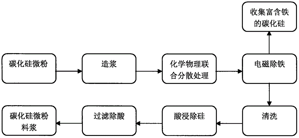
[0028] (1) Pulping: the particle size after grinding by Raymond mill is D 3 ≤14.8μm, D 94 ≥4.8μm silicon carbide micropowder and deionized water were mixed evenly for 30 minutes to prepare a silicon carbide micropowder slurry with a mass concentration of 25%;

[0029] (2) Dispersion treatment: add sodium pyrophosphate with a silicon carbide mass fraction of 0.6% to the uniform silicon carbide micropowder slurry prepared above, and stir evenly for 40 minutes;

[0030] (3) Electromagnetic iron removal: the silicon carbide micro-powder slurry obtained from the above dispersion is pumped at a distance of 4.5m 3 The / h flow rate is injected into the electromagnetic magnetic separator for iron removal, and the purified silicon carbide micro-powder slurry and the iron-rich silicon carbide micro-powder slurry are respectively obtained;

[0031] (4) Cleaning: Add deionized water to the purified silicon carbide micropowder slurry obtained after the above iron removal, stir evenly, let...

Embodiment 2

[0036] (1) Pulping: the particle size after grinding by Raymond mill is D 3 ≤14.8μm, D 94 ≥4.8μm silicon carbide micropowder and deionized water were uniformly stirred for 35 minutes and mixed to prepare a silicon carbide micropowder slurry with a mass concentration of 35%;

[0037] (2) Dispersion treatment: add sodium hexametaphosphate with a silicon carbide mass fraction of 0.5% to the uniform silicon carbide micropowder slurry prepared above, and stir evenly for 45 minutes;

[0038] (3) Electromagnetic iron removal: the silicon carbide micro-powder slurry obtained from the above dispersion is pumped at a distance of 4.5m 3 The / h flow rate is injected into the electromagnetic magnetic separator for iron removal, and the purified silicon carbide micro-powder slurry and the iron-rich silicon carbide micro-powder slurry are respectively obtained;

[0039] (4) Cleaning: add deionized water to the purified silicon carbide micropowder slurry obtained after the above iron remova...


PUM


Abstract

The invention relates to a method for removing iron and silicon impurities in silicon carbide micropowder for crystalline silicon wire cutting. The iron and silicon impurities in the silicon carbide powder are removed through combination of physical iron removal and chemical silicon removal. The method comprises the specific process as follows: the silicon carbide micropowder ground by a Raymond mill is mixed with deionized water for slurry making; a dispersant is added to obtained silicon carbonate micropowder slurry for stirring dispersion treatment; the dispersed silicon carbonate micropowder slurry is pumped into an electromagnetic separator for iron removal by magnetic separation; then the iron-removed and purified silicon carbonate micropower slurry is washed with water; acid is added to the silicon carbonate micropower slurry for acid leaching; finally, the purified silicon carbonate micropowder slurry is obtained through filtration. The method is simple to operate, high in production efficiency, low in cost and good in environmental benefit, and the use chemicals are reduced. The treated silicon carbonate powder product is stable in quality and suitable for industrial production, and the technical indexes meet the process requirement.

Description

technical field [0001] The invention relates to a method for removing iron and silicon impurities in silicon carbide micropowder, in particular to a method for removing iron and silicon impurities in silicon carbide micropowder for crystalline silicon wire cutting. Background technique [0002] Silicon carbide (SiC), commonly known as corundum, is widely used in grinding fields such as polishing wheels and multi-wire cutting because of its excellent properties such as high strength, high hardness, wear resistance, corrosion resistance, oxidation resistance, high thermal conductivity and good thermal stability. And it is widely used in non-grinding fields such as mechanical electronics, energy and environmental protection, and electronic semiconductors. In recent years, with the intensification of the global greenhouse effect and conventional energy crisis, solar energy, as a renewable energy source, has unlimited and environmental advantages, making the photovoltaic industry...

Claims


Application Information

Patent Timeline
Patent Type & Authority Applications(China)
IPC IPC(8): C01B32/956
CPCC01P2006/80
Inventor 赵银福赵新亚刘亚伟王品昌战友曹小冬张新忠李兵
Owner JIANGXI ENK NEW MATERIAL CO LTD
Learn More