


Quick Research
Generate reliable direction feasibility study reports for your R&D in just a few steps.

Technical Q&A
Discover and master advanced knowledge NOW. Basics, ideas, possibilities, all at once.

Find Solutions
As an expert in R&D theories, this can generate solutions to your technical problems instantly.

Evaluate Feasibility
Analyze your overall solution with one click, know your potential R&D risks in advance.

Monitor Landscape
Get weekly tech updates, stay abreast of the latest tech innovations and key insights.
Concave anvil used for forging and forging device
A technology for forging and concave surfaces, which is applied in forging/pressing/hammer devices, manufacturing tools, forging/pressing/hammering machinery, etc. It can solve the problems of unusable forgings, high processing costs, and sags in forgings, and simplify follow-up Processing flow, complete metal flow line, and the effect of eliminating elastic deformation
- Summary
- Abstract
- Description
- Claims
- Application Information
AI Technical Summary
Problems solved by technology
Method used
Image

Examples
Embodiment 1
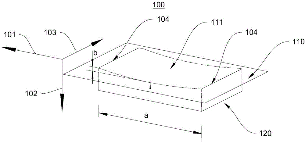
[0031] figure 1 It is a schematic structural diagram of the concave anvil 100 for forging provided in Embodiment 1 of the present invention. see figure 1 , this embodiment provides a forging concave anvil 100 for forging large forgings. The forging concave anvil 100 has a concave surface 111, a bottom surface 120 and defines a reference plane 110. The reference plane 110 is opposite to the concave surface 111.
[0032] In this embodiment, the concave anvil 100 for forging generally has a cuboid structure as a whole. The concave anvil 100 for forging extends along the first direction 101, and has a length a in the first direction 101, and the concave anvil 100 for forging has a thickness formed between the concave surface 111 and the bottom surface 120 along the second direction 102, along the third direction 103 has width.
[0033] The concave surface 111 is a surface depressed in the second direction 102 , and the distance between it and the reference plane 110 gradually a...
Embodiment 2
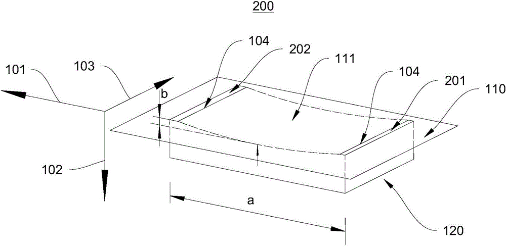
[0044] figure 2 It is a schematic structural diagram of the concave anvil 200 for forging provided in the second embodiment of the present invention. see figure 2 The main difference between the forging concave anvil 200 provided in this embodiment and the forging concave anvil 100 provided in the first embodiment lies in the concave surface 111 .
[0045] In this embodiment, the concave anvil 200 for forging also has a first plane 201 and a second plane 202 . The concave surface 111 extends along the first direction 101 , and the edges 104 of two sides of the concave surface 111 coincide with the first plane 201 and the second plane 202 respectively.
[0046] In this embodiment, both the first plane 201 and the second plane 202 are on the same plane, and both are coplanar with the reference plane 110 . In other embodiments of the present invention, the relative positional relationship between the first plane 201 and the second plane 202 can be changed according to the si...
Embodiment 3
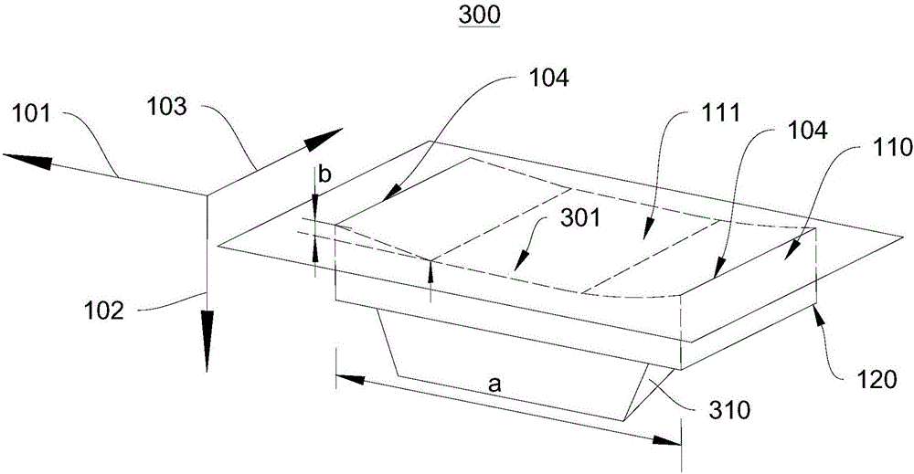
[0052] image 3 It is a structural schematic view of the first viewing angle of the concave anvil 300 for forging provided by the third embodiment of the present invention. see image 3 One difference between the forging concave anvil 300 provided in this embodiment and the forging concave anvil 100 provided in Embodiment 1 lies in the concave surface 111 . In this embodiment, the concave surface 111 also has a planar region 301 , and the planar region 301 is relatively parallel to the reference plane 110 . The distance between the planar area 301 and the reference plane 110 is constant, and the distance is equal to the maximum distance between the concave surface 111 and the reference plane 110 . That is, in the second direction 102 , relative to the reference plane 110 , the concave surface 111 has a maximum depth b equal to the distance between the plane region 301 and the reference plane 110 .
[0053] Figure 4 A schematic structural diagram of the second viewing angl...
PUM
 Abstract
Description
Claims
Application Information
 - R&D Engineer
- R&D Manager
- IP Professional
- Industry Leading Data Capabilities
- Powerful AI technology
- Patent DNA Extraction
Browse by: Latest US Patents, China's latest patents, Technical Efficacy Thesaurus, Application Domain, Technology Topic, Popular Technical Reports.
© 2024 PatSnap. All rights reserved.Legal|Privacy policy|Modern Slavery Act Transparency Statement|Sitemap|About US| Contact US: help@patsnap.com