
Patsnap Eureka
For R&D, Patsnap Eureka makes reading and utilizing patents & technical documents easy.
Patsnap Eureka AIR
Designed for self-driven R&D workflows. Generate viable solutions, solve complex R&D challenges, empower your innovation with AI.

Patsnap Eureka Materials
Designed for material experts only. Revolutionize your material R&D, from search, analyze, to developing new materials.

TechResearch
Generate reliable direction feasibility study reports for your R&D in just a few steps.

TechSeek
Discover and master advanced knowledge NOW. Basics, ideas, possibilities, all at once.

TechMind
As an expert in R&D Theories, TechMind can generates customized viable solutions instantly.

TechRisk
Analyze your overall solution with one click, know your potential R&D risks in advance.

TechMonitor
Get weekly tech updates, stay abreast of the latest tech innovations and key insights.
punching machine
A punching machine and punching die technology, which is applied in the field of punching machines, can solve the problems of split punching machine structure and complex oil circuit, etc., and achieve the effects of reducing volume, reducing the probability of oil leakage, and being convenient to use
- Summary
- Abstract
- Description
- Claims
- Application Information
AI Technical Summary
Problems solved by technology
Method used
Image

Examples
Embodiment Construction
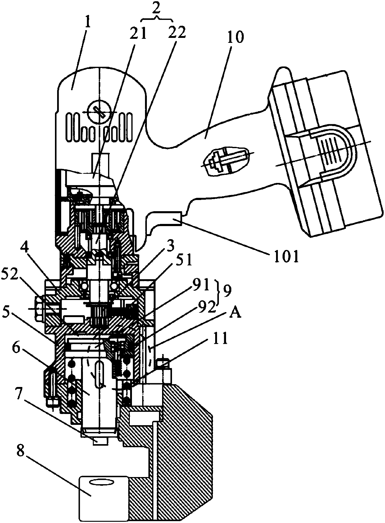
[0020] Such as figure 1 As shown, the punching machine provided in this embodiment includes a housing 1 , a drive assembly 2 , an eccentric shaft 3 , an oil cylinder 4 , a hydraulic pump 5 , a push shaft 6 , an upper die 7 , a lower die 8 and an oil return assembly 9 . The driving assembly 2 is arranged in the casing 1 . The eccentric shaft 3 is connected to the drive assembly 2 . The oil cylinder 4 is arranged in the casing 1 . The hydraulic pump 5 includes a plurality of piston assemblies 51 arranged in the circumferential direction of the eccentric shaft 3, each piston assembly 51 has a plurality of oil holes communicating with the oil cylinder 4 (due to the problem of angle, the figure is not shown), the eccentric shaft 3 The rotation drives the multiple piston assemblies 51 to move in a direction perpendicular to the axis of the eccentric shaft, squeezing the oil in the oil cylinder 4 into the oil chamber 52 of the hydraulic pump 5 . The push shaft 6 is arranged in the...
PUM
 Abstract
Description
Claims
Application Information
 - R&D Engineer
- R&D Manager
- IP Professional
- Industry Leading Data Capabilities
- Powerful AI technology
- Patent DNA Extraction
Browse by: Latest US Patents, China's latest patents, Technical Efficacy Thesaurus, Application Domain, Technology Topic, Popular Technical Reports.
© 2024 PatSnap. All rights reserved.Legal|Privacy policy|Modern Slavery Act Transparency Statement|Sitemap|About US| Contact US: help@patsnap.com