Cathode hanging system for wet dust remover non-tension device
A technology of wet dust collector and tensioning device, which is applied in the direction of electrode conveying device, external electrostatic separator, electrostatic separation, etc., can solve the risk of increasing condensation and creepage of cathode system, poor anti-sway performance of tensioning device, and reactor size Major problems, to achieve the effect of reducing the amount of maintenance projects, reducing maintenance costs, and saving project costs
- Summary
- Abstract
- Description
- Claims
- Application Information
AI Technical Summary
Problems solved by technology
Method used
Image
Examples
Embodiment 1
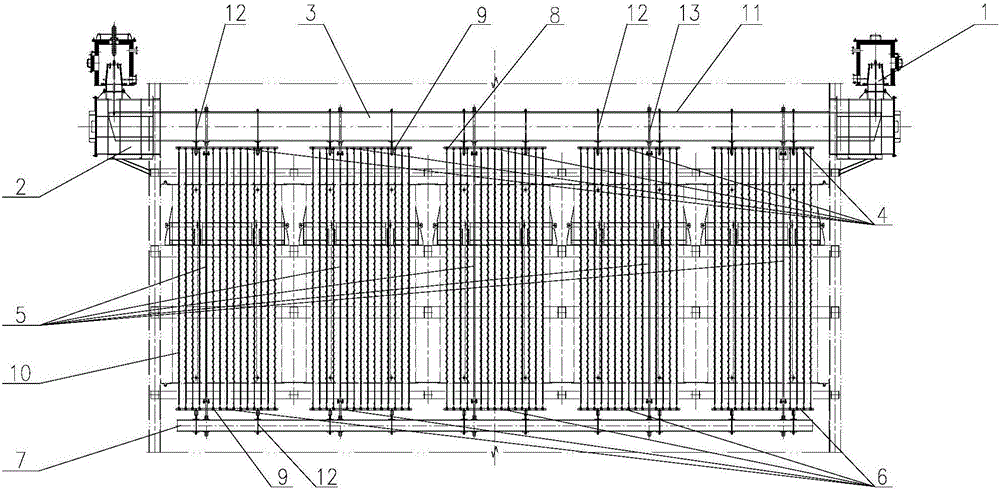
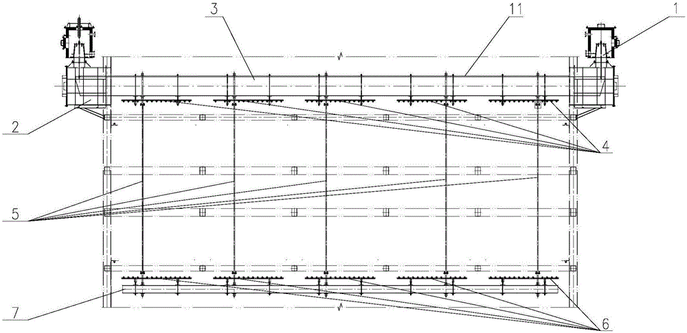
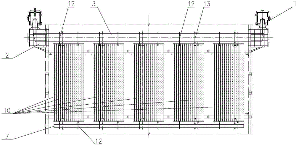
[0021] Embodiment 1 of the present invention: as Figure 1 to Figure 5 As shown, the wall penetration protection device 2 is welded on both sides of the shell wall of the wet dust collector, the insulator box suspension system 1 is arranged on the wall penetration protection device 2, and the upper cathode main beam 3 is arranged between the insulator box suspension system 1. The upper cathode frame 4 is suspended from the lower part of the cathode main beam 3 , and the lower cathode frame 6 is suspended from the upper cathode main beam 3 through the suspension rod 5 , and the cathode wire 10 is placed between the upper cathode frame 4 and the lower cathode frame 6 . The upper surface of the upper cathode main beam 3 is also tiled with a conductive device 11 made of stainless steel, which mainly plays a conductive role. The length of the conductive device 11 is equal to the length of the upper cathode main beam 3 . The suspension rod 5 has a diameter of 40mm, a thickness of 4m...
Embodiment 2
[0022] Embodiment 2: as figure 1 As shown, the cathode suspension system for the tension-free device of the wet dust collector includes an insulator box suspension system 1, a wall penetration protection device 2, an upper cathode main beam 3, an upper cathode frame 4, a suspension rod 5, and a lower cathode frame 6 and cathode wire 10. The wall penetration protection device 2 is welded on both sides of the shell wall of the wet dust collector. The insulator box suspension system 1 is arranged on the wall penetration protection device 2. The upper cathode main beam 3 is arranged between the insulator box suspension system 1, and the upper cathode main beam 3. The upper cathode frame 4 is suspended from the lower part, and the upper cathode main beam 3 is also suspended from the lower cathode frame 6 through the suspension rod 5. The cathode wire 10 is placed between the upper cathode frame 4 and the lower cathode frame 6.
Embodiment 3
[0023] Embodiment 3: as figure 1 with figure 2 As shown, the wall penetration protection device 2 is welded on both sides of the shell wall of the wet dust collector, the insulator box suspension system 1 is arranged on the wall penetration protection device 2, and the upper cathode main beam 3 is arranged between the insulator box suspension system 1. The upper cathode frame 4 is suspended from the lower part of the cathode main beam 3 , and the lower cathode frame 6 is suspended from the upper cathode main beam 3 through the suspension rod 5 , and the cathode wire 10 is placed between the upper cathode frame 4 and the lower cathode frame 6 . The lower cathode frame 6 is also hung with the lower cathode main beam 7, the lower cathode frame 6 is stabilized by the suspender 5 and the lower cathode main beam 7, and the setting of the lower tensioning device with poor safety factor is cancelled, which improves the suspension of the wet dust collector. hanging stability. The sy...
PUM
 Abstract
Description
Claims
Application Information
 - Generate Ideas
- Intellectual Property
- Life Sciences
- Materials
- Tech Scout
- Unparalleled Data Quality
- Higher Quality Content
- 60% Fewer Hallucinations
Browse by: Latest US Patents, China's latest patents, Technical Efficacy Thesaurus, Application Domain, Technology Topic, Popular Technical Reports.
© 2025 PatSnap. All rights reserved.Legal|Privacy policy|Modern Slavery Act Transparency Statement|Sitemap|About US| Contact US: help@patsnap.com


