
Combustor for household gas stove

A technology of gas stoves and burners, which is applied in the direction of gas fuel burners, burners, and combustion methods, and can solve the problems of affecting human health, wasting gas, and uneven heating of the bottom of the pot, etc.

Inactive Publication Date: 2017-02-15
ZHEJIANG YITIAN INTELLIGENT KITCHEN ELECTRICITY CO LTD
View PDF6 Cites 2 Cited by
  • Summary
  • Abstract
  • Description
  • Claims
  • Application Information

AI Technical Summary

Problems solved by technology

The problem is: when cooking, the bottom of the pot is heated unevenly, mainly because there is no fire hole distribution between the outer ring fire hole and the inner ring fire hole, and the space without fire hole distribution corresponds to a larger area and the flame does not directly contact. to the bottom of the pot, so the place that does not touch the flame receives less heat, and the flames from the outer ring fire hole and the inner ring fire hole directly contact the bottom of the pot, and the heat received will be high, which will inevitably cause uneven heating of the bottom of the pot , in order to ensure the degree of cooked food, the user needs to spend a long time wasting a lot of gas for cooking. In the social atmosphere that advocates the concept of energy saving and environmental protection, the use of this kind of burner is obviously not conducive to the market competition of products. In addition, using this kind of burner is obviously not conducive to the market competition of products. This kind of burner also has the problem of insufficient combustion of gas, which can easily produce toxic and harmful gases, which will affect human health and reduce the safety of the product.

Method used


Image

  • Combustor for household gas stove
  • Combustor for household gas stove
  • Combustor for household gas stove

Examples


Embodiment Construction

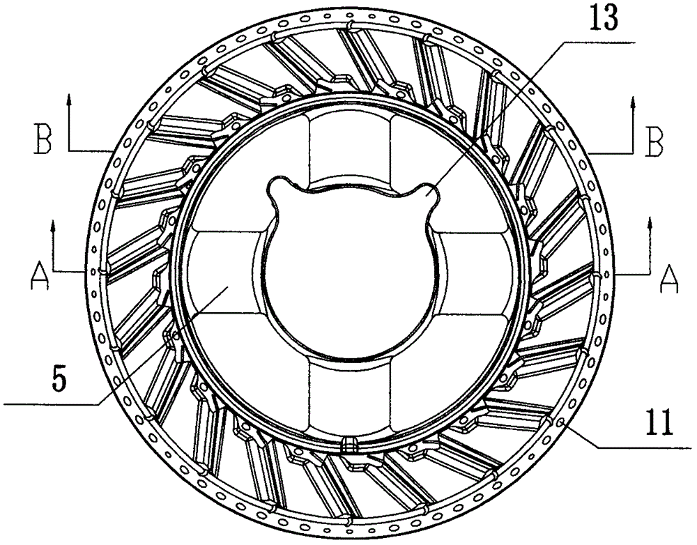
[0019] refer to figure 1 , figure 2 , image 3 , Figure 4 , Figure 5 , Figure 6 As shown, a burner for a household gas stove includes an inner fire cover seat 1 and an outer fire cover seat 2, the inner fire cover seat 1 has an inner fire cover 3, and the outer fire cover seat 2 has an outer fire cover 4 , the inner fire cover seat 1 and the outer fire cover seat 2 are connected by a gas channel 5, the bottom of the inner fire cover seat 1 has an air intake channel 6, and the top surface of the outer fire cover 4 is a slope inclined from outside to inside 7. There is a ring of L-shaped bosses 8 evenly distributed along the circumferential direction of the fire cover on the slope 7 and protruding from the slope 7. The L-shaped bosses 8 are arranged obliquely on the slope 7 to form a gathering shape. There are linear fire outlet holes 9 and circular fire outlet holes 10 on the L-shaped boss 8, and a circle of outer fire outlet holes 11 evenly distributed along the circu...


PUM


Abstract

The invention discloses a combustor for a household gas stove. The combustor comprises an inner fire cover base and an outer fire cover base. The inner fire cover base is provided with an inner fire cover. The outer fire cover base is provided with an outer fire cover. The inner fire cover base and the outer fire cover base are connected through a fuel gas channel. The bottom of the inner fire cover base is provided with a gas input channel. The top face of the outer fire cover is a slope inclining from outside to inside. The slope is provided with a circle of L-shaped bosses which are distributed uniformly in the circumferential direction of the fire cover and protrude out of the slope. The L-shaped bosses are arranged on the slope in an inclined manner to form a rounding-up shape. Each L-shaped boss is provided with a linear fire output hole and a round fire output hole. The circumferential face of the outer fire cover is provided with a circle of outer fire output holes distributed uniformly in the circumferential direction. By the adoption of the structure, distribution of the fire output holes of the outer ring fire cover and the fire output holes of the inner ring fire cover is improved, the fire output holes can be distributed more uniformly, the heating area of the pot bottom is more uniform, and the heat efficiency is improved.

Description

technical field [0001] The invention discloses a burner for a household gas cooker, which belongs to the technical field of the household gas cooker. Background technique [0002] At present, a burner for a gas stove includes a fire cover seat, an outer ring fire cover and an inner ring fire cover installed on the fire cover seat, the outer ring fire cover has an outer ring fire outlet, an inner ring fire outlet, and an inner ring fire The cover has a fire hole. The problem is: when cooking, the bottom of the pot is heated unevenly, mainly because there is no fire hole distribution between the outer ring fire hole and the inner ring fire hole, and the space without fire hole distribution corresponds to a larger area and the flame does not directly contact. to the bottom of the pot, so the place that does not touch the flame receives less heat, and the flames from the outer ring fire hole and the inner ring fire hole directly contact the bottom of the pot, and the heat recei...

Claims


Application Information

Patent Timeline
IPC IPC(8): F23D14/26F23D14/46
CPCF23D14/26F23D14/46
Inventor 陈月华徐海
Owner ZHEJIANG YITIAN INTELLIGENT KITCHEN ELECTRICITY CO LTD
Learn More