
Industrial gas ultra-low nitrogen energy-saving spiral combustion head and burner

An industrial gas and combustion head technology, which is applied to gas fuel burners, burners, combustion methods, etc., can solve the problems of high temperature production, loss of heat energy, waste of gas, etc., so as to reduce the content of nitrogen oxides and reduce high temperature. area, the effect of increasing the burning area

Active Publication Date: 2018-03-06
江苏弗雷姆环境科技有限公司
View PDF7 Cites 0 Cited by
  • Summary
  • Abstract
  • Description
  • Claims
  • Application Information

AI Technical Summary

Problems solved by technology

However, because it is easy to cause too much fuel, a large amount of nitrogen oxides and carbon monoxide are produced, which not only causes environmental pollution, but also wastes gas, and the excess of air also causes a large amount of heat taken away by the exhaust gas.
At present, air and gas are commonly used in domestic industrial production to reduce the surface temperature of the flame, which has achieved ultra-low nitrogen oxide generation (that is, ultra-low nitrogen burner), and this nitrogen reduction method is to waste more heat energy and waste gas At the same time, this nitrogen reduction method cannot be realized for high-temperature production (such as petrochemical cracking furnaces, glass furnaces)

Method used


Image

  • Industrial gas ultra-low nitrogen energy-saving spiral combustion head and burner
  • Industrial gas ultra-low nitrogen energy-saving spiral combustion head and burner
  • Industrial gas ultra-low nitrogen energy-saving spiral combustion head and burner

Examples


Embodiment Construction

[0025] The present invention will be further described below in conjunction with the accompanying drawings.

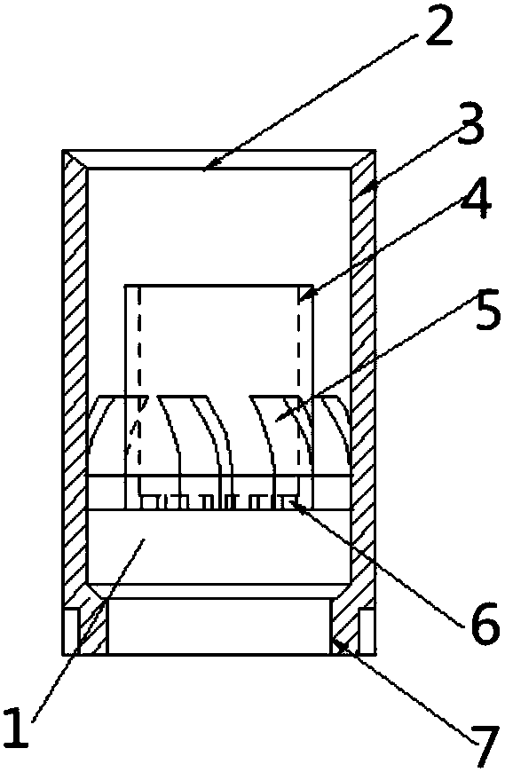
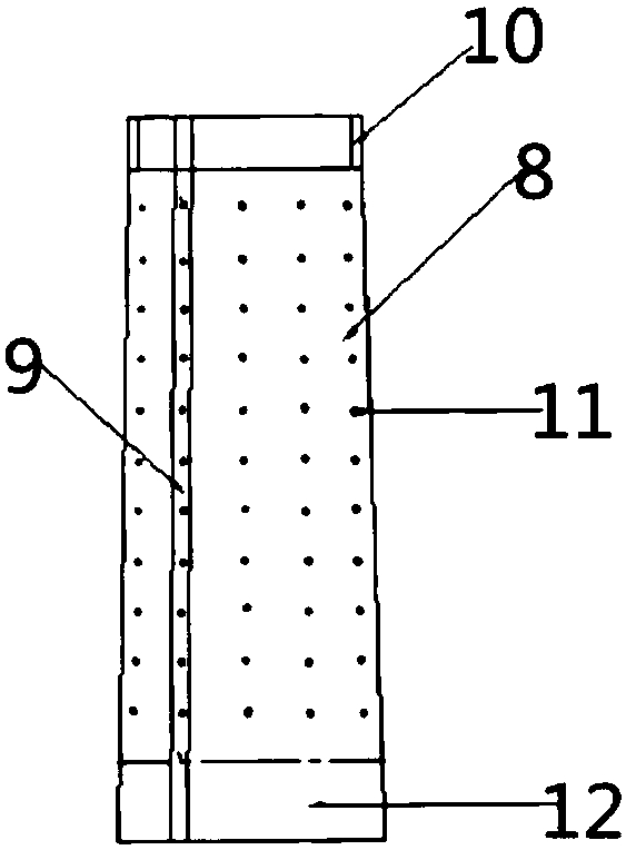
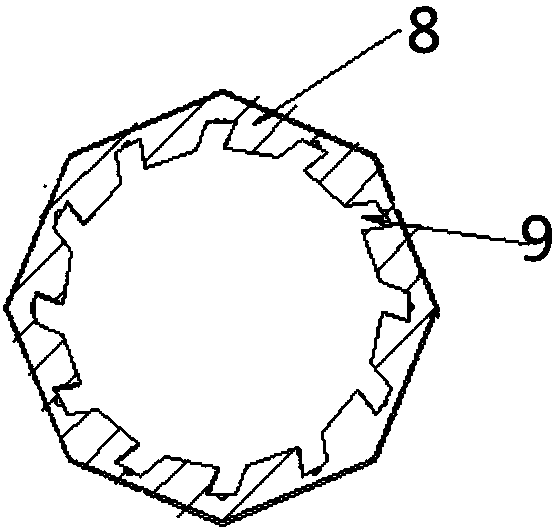
[0026] Such as Figure 1-7 As shown, the reference signs are as follows: spiral combustion head 1, fire outlet 2, cylindrical outer wall 3, cylindrical inner wall 4, spiral protrusion 5, air outlet 6, combustion head connecting section 7, combustion rod 8, gas chute 9. Combustion rod connection section 10, combustion hole 11, pouring connection section 12, primary air distribution port 13, gas nozzle 14, secondary air distribution port 15, tertiary air distribution port 16, premixing section 17, contraction section 18, mixed gas outlet 19 , expansion section 20, advection section 21, air inlet pipe 22, air chamber 23, air inlet 24, long open flame pipe 25, ignition hole 26, observation hole 27, gas chamber 28, conical control valve 29, air inlet 30, gas Metal pipe 31, burner shell 32, ceramic wool insulation layer 33, heat-insulating refractory pouring material 34, pr...


PUM


Abstract

The invention discloses an industrial gas ultralow-nitrogen energy-saving spiral combustion head and belongs to the technical field of gas combustion devices. The spiral combustion head comprises an outer cylindrical wall; an inner cylindrical wall is sleeved inside the outer cylindrical wall; the outer cylindrical wall and the inner cylindrical wall are connected into an integrated structure through a spiral bulge; air outlet holes are uniformly distributed in the bottom of the inner cylindrical wall; a fire outlet hole is formed in the top of the outer cylindrical wall; and the bottom of the outer cylindrical wall is provided with a combustion head connecting section. The invention also discloses a combustor comprising the spiral combustion head. By using the spiral combustion head disclosed by the invention, a flame rotates in a fixed direction, so that the heat exchange efficiency is increased, and the utilization ratio of heat energy is increased; meanwhile the combustion speed of the flame is stabilized, so that flame lifting and backfire are avoided; by using the combustor comprising the spiral combustion head, the radiated heat energy can be increased, so that a nitrogen reducing effect is achieved; and air and gases are sufficiently and uniformly stirred in a mixing pipe, so that an air / fuel ratio approaching to a theoretical value is achieved.

Description

technical field [0001] The invention belongs to the technical field of gas combustion devices, and in particular relates to an industrial gas ultra-low nitrogen energy-saving spiral combustion head and a burner. Background technique [0002] At present, the combustion methods of all combustion devices using gas as thermal energy in industrial production are nothing more than two methods of premixing and direct injection. These two combustion methods cannot accurately control the air-fuel mixing ratio and mixing uniformity, resulting in gas overheating. Too much or too much air will cause the loss of fuel or heat energy. At the same time, the nitrogen oxides in the flue gas are too high. [0003] In the premixing device of the prior art, although the air-fuel ratio can be adjusted appropriately through the damper and the gas valve, the full combustion of the gas cannot be achieved by mixing the two gases properly, but by fully mixing and stirring the two gases. Evenly, that ...

Claims


Application Information

Patent Timeline
Patent Type & Authority Patents(China)
IPC IPC(8): F23D14/02F23D14/48F23D14/64F23D14/60
CPCF23D14/02F23D14/48F23D14/60F23D14/64F23D2203/007
Inventor 李志友
Owner 江苏弗雷姆环境科技有限公司
Learn More