
Boiler burning system

A boiler combustion and boiler technology, applied in the direction of combustion methods, control combustion, combustion equipment, etc.

Active Publication Date: 2017-02-15
杭州红山热电有限公司
View PDF8 Cites 3 Cited by
  • Summary
  • Abstract
  • Description
  • Claims
  • Application Information

AI Technical Summary

Problems solved by technology

[0004] In view of the deficiencies in the prior art, the purpose of the present invention is to provide a boiler combustion system, which aims to solve the problems of boiler combustion speed control and efficient utilization of heat energy

Method used


Image

  • Boiler burning system
  • Boiler burning system
  • Boiler burning system

Examples


Embodiment Construction

[0048] The present invention will be described in detail below in conjunction with the accompanying drawings and embodiments.

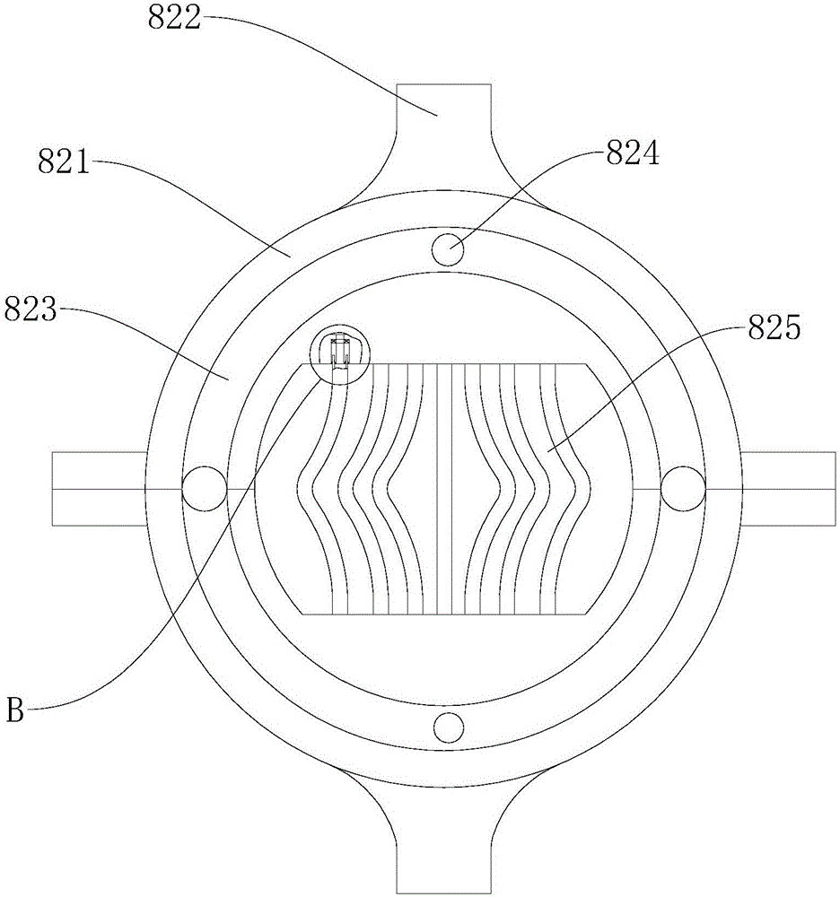
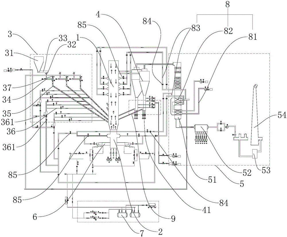
[0049] A boiler combustion system, such asfigure 1 As shown, including boiler 1, the bottom of boiler 1 is provided with air chamber 2, and the part of boiler 1 near air chamber 2 is provided with feeding system 3, boiler 1 is connected with cyclone separator 4, and tail gas treatment is provided at the end of cyclone separator 4 System 5, air chamber 2 is connected to an ignition system, and exhaust gas treatment system 5 is connected to a thermal circulation system, which is connected to boiler 1, cyclone separator 4, ignition system and feeding system 3 respectively. The boiler 1 is fed through the feeding system 3, and then ignited by the igniter 6 at the position of the air chamber 2, and the ignited fuel is blown up through the air chamber 2, let it rise, and flow in the boiler 1, so that the coal is burned by The original static state becomes d...


PUM


Abstract

The invention discloses a boiler burning system, which can return part of ash to a boiler through an ash returning device, and the other part of ash is discharged from an ash outlet, so as to achieve control over an ash returning amount, in addition, through arranging an air tube, heat of tailgas is absorbed and is returned back to a charging system for heating coal, the coal can be preheated, air of an igniter can be preheated, the igniter can be ignited more easily, and the other part is flushed and comes back to the boiler, such that the air entering the boiler is air instead of cold air, preheating is not required, no damage is generated to the boiler, loss of burning heat of the coal is reduced, and a use rate of the heat energy is improved.

Description

technical field [0001] The invention relates to the field of combustion equipment, more specifically, it relates to a boiler combustion system. Background technique [0002] The boiler is an indispensable piece of equipment in many productions that require the use of steam. By burning fuel, steam will be evaporated for production. In the process of steam generation, the combustion status of the boiler has a great influence on the generation of steam and the utilization rate of fuel. There is a very significant impact. [0003] The Chinese patent with the publication number CN104315505A discloses a circulating fluidized bed boiler, which includes a furnace chamber, a feeding device, a combustion chamber, a cyclone separator, and a tail flue arranged in sequence from front to back, and the furnace is a fully suspended water-cooled wall. Wind caps are evenly arranged on the air distribution plate of the water-cooled wall, and a high-temperature superheater is suspended above t...

Claims


Application Information

Patent Timeline
Patent Type & Authority Applications(China)
IPC IPC(8): F23B70/00F23J15/02F23J15/06F23K3/14F23N5/18
CPCF23B70/00F23J15/022F23J15/06F23K3/14F23K2201/101F23N5/18F23N2005/181Y02E20/30Y02E20/34
Inventor 全天宝顾建平
Owner 杭州红山热电有限公司
Learn More