Inner by-pass valve type magnetorheological fluid suspension

A magnetorheological fluid and channel technology, applied in springs, shock absorbers, springs/shock absorbers, etc., can solve the problems of increasing the zero-field dynamic stiffness of the suspension, increasing the production cost, and the large volume of the upper liquid chamber. Achieve the effect of reducing the zero-field dynamic stiffness of the mount, the large-zero field dynamic stiffness, and the simple structure of the piston

Active Publication Date: 2017-02-15
HEFEI UNIV OF TECH
View PDF8 Cites 6 Cited by
  • Summary
  • Abstract
  • Description
  • Claims
  • Application Information

AI Technical Summary

Problems solved by technology

The magneto-rheological fluid mount with this structure does not solve the problem of blockage of the damping hole or inertial channel during high-frequency vibration. Even with the addition of a decoupler, the resonance of the liquid will still increase the zero-field motion of the mount. Stiffness; at the same time, due to the blockage of the damping hole or inertial channel, the adjustable range of the damping force of the magnetorheological fluid mount of this structure is limited; moreover, due to the large volume of the upper liquid chamber, the magnetorheological fluid mount of this structure needs to use A large amount of magnetorheological fluid increases the production cost of the mount
[0004] Based on this, the Chinese invention patent "engine magnetorheological hydraulic mount based on extrusion mode", publication number: CN103148158A, discloses a magnetorheological fluid extrusion mount for automobile powertrain mount system. The suspension is equipped with upper and lower extrusion pole plates, inertial channels and decoupling membranes, and the extrusion motion of magnetorheological fluid in the upper and lower extrusion pole plates does not interfere with the flow motion of magnetorheological fluid in the inertial channel, so even In the case of blockage of

Method used


Image

  • Inner by-pass valve type magnetorheological fluid suspension
  • Inner by-pass valve type magnetorheological fluid suspension
  • Inner by-pass valve type magnetorheological fluid suspension

Examples


Embodiment Construction

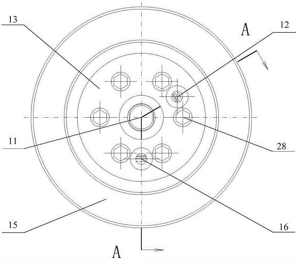
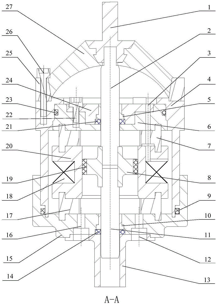
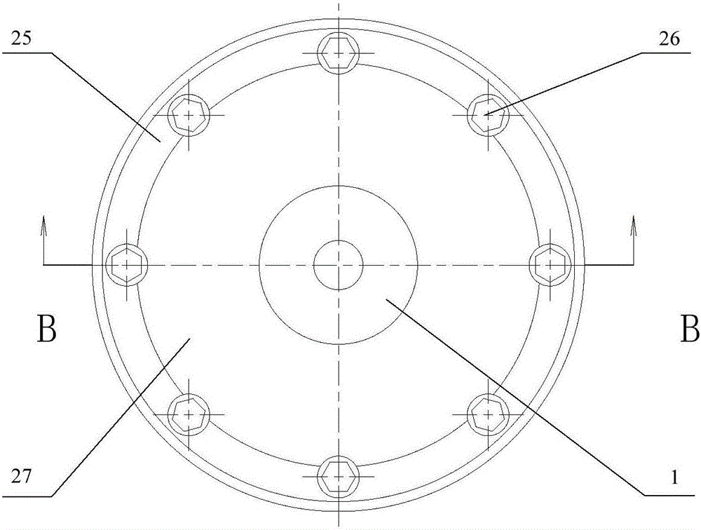
[0032] see Figure 1a , Figure 1b , Figure 2a and Figure 2b , the structural form of the inner bypass channel valve magneto-rheological fluid mount in this embodiment is:

[0033] The magnetorheological fluid unit is set to realize damping control. The upper end cover 6 and the lower end cover 15 are arranged one by one at the upper and lower ends of the outer cylinder body 4 to form a closed hydraulic chamber with constant volume, and the hydraulic chamber is filled with magnetorheological fluid. Liquid; the inner cylinder 20 is concentrically arranged in the outer cylinder 4, and an annular flow channel is formed between the inner side wall of the outer cylinder 4 and the outer side wall of the inner cylinder 20; between the top end surface of the inner cylinder 20 and the upper end cover 6 A plurality of upper isolation blocks 7 are arranged at intervals along the circumference, and a plurality of lower isolation blocks 17 are arranged at intervals along the circumferenc...


PUM


Abstract

The invention discloses an inner by-pass valve type magnetorheological fluid suspension. The inner by-pass valve type magnetorheological fluid suspension is characterized in that according to a magnetorheological fluid unit, a hydraulic cavity is formed by an outer cylinder block, an inner cylinder barrel is concentrically arranged in the outer cylinder block, and an annular runner is formed between the outer cylinder block and the inner cylinder barrel; a magnetic exciting coil is embedded in an annular groove in the periphery of the inner cylinder barrel, and the magnetic exciting coil produces a magnetic field to enable magnetorheological fluid in the annular runner to work in a flow pattern; a rubber main spring in a rubber unit with bearing static loads is located on the exterior of the hydraulic cavity; and a piston rod and a piston form a piston mechanism, the piston axially moves in the inner cylinder barrel to drive the magnetorheological fluid in the hydraulic cavity to flow between the annular channel and an inner cavity of the inner cylinder barrel, and parallel action between the piston mechanism and the magnetorheological fluid unit is achieved. The inner by-pass valve type magnetorheological fluid suspension can control the damping force of the magnetorheological fluid, the dynamic rigidity of the suspension can be controlled, and the inner by-pass valve type magnetorheological fluid suspension has a large damping force control range, a maximal operating stroke and small null field dynamic rigidity.

Description

technical field [0001] The invention relates to the technical field of using magnetorheological fluid for vibration reduction, in particular to a valve-type magnetorheological fluid mount used for engine mount systems of automobiles, ships, engineering machinery and the like. Background technique [0002] Hydraulic mounts are currently widely used in engine mount systems such as automobiles, ships, and construction machinery. Compared with cheap rubber mounts, hydraulic mounts exhibit greater damping characteristics under low-frequency excitation, which inhibits the mounting system to a certain extent. Under high-frequency excitation, due to the blockage of the damping hole or the inertia channel, the large stiffness characteristic of the hydraulic mount deteriorates the high-frequency vibration isolation performance of the mount system. Compared with ordinary suspension liquids, magnetorheological fluids are smart materials with adjustable rheological properties. Under the ...

Claims


Application Information

Patent Timeline
IPC IPC(8): F16F9/53
CPCF16F9/535F16F9/537
Inventor 钱立军白先旭陈朋杨森沈升
Owner HEFEI UNIV OF TECH
Why Eureka
Try Eureka