Medical image in-vitro positioning identification point with compatibility

A medical image and external positioning technology, applied in medical science, instruments and sensors for radiological diagnosis, etc., can solve the problems of lack of versatility, complex production process, inconvenient use, etc., to get rid of the on-site configuration process, imaging Clear, easy-to-use effects

Inactive Publication Date: 2017-02-15
ANHUI YOUNIKE MEDICAL TECH CO LTD
View PDF1 Cites 2 Cited by
  • Summary
  • Abstract
  • Description
  • Claims
  • Application Information

AI Technical Summary

Problems solved by technology

[0005] To sum up, the current medical in vitro positioning point device is not only complicated in manufacturing process, but also inconvenient to use, and it is not compatible with X-ray, CT, DST, CT / MRI, MRI and other imaging equipment currently used in medical institutions. , not universal

Method used


Image

  • Medical image in-vitro positioning identification point with compatibility
  • Medical image in-vitro positioning identification point with compatibility
  • Medical image in-vitro positioning identification point with compatibility

Examples


Embodiment 1

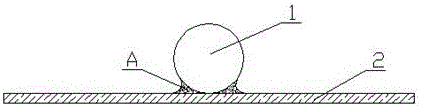
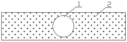
[0038] Such as figure 1 and figure 2 As shown, a compatible medical image in vitro positioning marking point in this embodiment includes an imaging part 1. The imaging part 1 is a hollow body made of an imaging material whose density is greater than that of human tissue, and mainly plays an imaging role. The hollow body can be imaged using the principle of refraction in CT / MRI and MRI imaging, and has compatibility and versatility with existing medical institution X-ray, CT, DST, CT / MRI, MRI and other imaging equipment, effectively avoiding similar problems in the market. Image positioning products have shortcomings such as inaccurate marking, incompatibility with imaging equipment, overly complicated operations, heavy metal lead pollution, etc., and do not pollute patients, the environment and equipment, and are easy to use. In this embodiment, the imaging part 1 is a hollow sphere, with clear imaging and accurate positioning. The same positioning point can replace the moda...

Embodiment 2

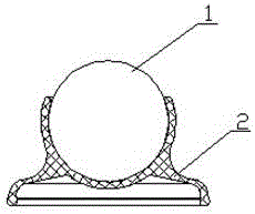
[0041] Such as image 3 , Figure 4 and Figure 5 As shown, a compatible medical image in vitro positioning marking point of this embodiment has the same basic structure as that of Embodiment 1, except that:

[0042] The fixing part 2 in this embodiment is a fixing seat, and the imaging part 1 is connected with the fixing seat by interference fit. The fixing base is made of soft material, and the fixing base has a cavity capable of wrapping and fixing the imaging part 1. When the imaging part 1 is forcibly assembled into the cavity of the fixing base, the cavity of the fixing base can tightly wrap Imaging part 1. The bottom of the fixed seat is a suction cup structure. When in use, press on the fixed seat. The suction cup structure at the bottom of the fixed seat is compressed by force and can fully contact the human skin. After the pressure is released, the suction cup structure at the bottom of the fixed seat produces recovery elasticity and forms a vacuum suction. , so ...


PUM


Abstract

The invention discloses a medical image in-vitro positioning identification point with compatibility, which belongs to the technical field of medical equipment and medical treatment and public health. The positioning identification point comprises an imaging portion and a fixing portion capable of fixing the imaging portion at the surface of a human body, wherein the imaging portion is a hollow body which is made of an imaging material with density greater than the tissue density of the human body, and the hollow body can be imaged by using a secondary refraction principle; the imaging portion is a hollow sphere; the imaging material is glass, ceramics or zirconium oxide. The hollow body made of the imaging material with the density greater than the tissue density of the human body is used as the imaging portion, the hollow imaging portion can be imaged by using the secondary refraction principle of the hollow structure when in CT/MRI and MRI imaging, so that the medical image in-vitro positioning identification point is more compatible with the existing multi-mode image fusion imaging device, has universality, is unnecessary to replace when different modes are changed for scanning, more precise in positioning and more convenient to use.

Description

technical field [0001] The present invention relates to a medical image marking point, more specifically, relates to a medical image external positioning marking point with imaging compatibility of various medical equipment, which can be used for X-ray, CT, DST, CT / MRI, MRI and other equipment The positioning mark during imaging provides compatible image fusion and mark positioning for multi-modal medical image registration and fusion, and indirectly or directly provides doctors with accurate reference information and provides a basis for their decision-making. Background technique [0002] With the development of precision medicine, a variety of advanced medical imaging equipment provides medical imaging information of various modalities for clinical diagnosis. Multimodal medical image fusion is the application of image fusion technology to medical images. After fusion processing of medical images from different medical imaging equipment, new medical images containing more ...

Claims


Application Information

Patent Timeline
Patent Type & Authority Applications(China)
IPC IPC(8): A61B6/03A61B5/055
CPCA61B6/032A61B5/0035A61B5/055A61B6/482
Inventor 魏强魏刚何睿欣唐胜利傅远来傅强宋贤辉宋士赫
Owner ANHUI YOUNIKE MEDICAL TECH CO LTD
Why Eureka
Try Eureka