Engine local oil anti-emulsification system and using method thereof

An engine and anti-emulsification technology, applied in the direction of engine components, machine/engine, engine lubrication, etc., can solve the problems of inability to solve the problem of oil emulsification, insufficient ventilation, etc., to solve the problem of oil emulsification, improve the effect, gas utilization high rate effect

Active Publication Date: 2017-02-08
DONGFENG COMML VEHICLE CO LTD
View PDF7 Cites 1 Cited by
  • Summary
  • Abstract
  • Description
  • Claims
  • Application Information

AI Technical Summary

Problems solved by technology

[0007] The purpose of the present invention is to overcome the defects and problems in the prior art that cannot solve the problem of engine oil emulsification and insufficient ventilation, and provide a local engine oil anti-emulsification system and its use method that can solve the problem of engine oil emulsification and sufficient ventilation

Method used


Image

  • Engine local oil anti-emulsification system and using method thereof
  • Engine local oil anti-emulsification system and using method thereof
  • Engine local oil anti-emulsification system and using method thereof

Examples


Embodiment 1

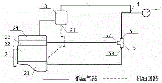
[0048] see Figure 1 to Figure 3 , a local engine oil anti-emulsification system, including an engine 2, a fresh air inlet 1 and an oil-gas separator 3, the engine 2 sequentially includes an oil pan 21, a cylinder block 22, a cylinder head 23, and a cylinder Cover 24, the cylinder head cover 24 communicates with the exhaust gas outlet 4 after the oil-gas separator 3, and the exhaust gas outlet 4 and the fresh air inlet 1 communicate with the cylinder head 23;

[0049] The anti-emulsification system also includes a three-way valve 5, the upper air inlet 51 of the three-way valve 5 communicates with the waste gas outlet 4 and the fresh air inlet 1, and the flat air outlet 52 of the three-way valve 5 communicates with the cylinder head 23 , The vertical air outlet 53 of the three-way valve 5 communicates with the oil pan 21 .

[0050] A method of using the local engine oil anti-emulsification system of the above-mentioned engine, the method of using includes replacing the exhaus...

Embodiment 2

[0053] Basic content is the same as embodiment 1, the difference is:

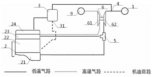
[0054] The anti-emulsification system also includes a supercharger 6, which includes a turbine 61 and a compressor 62 connected to each other, the air inlet of the compressor 62 communicates with the exhaust gas outlet 4 and the fresh air inlet 1, The gas outlet of the compressor 62 communicates with the upper air inlet 51 .

[0055] In use, the fresh air or the separated waste gas flows through the compressor 62 to increase the pressure before it flows into the upper air inlet 51 .

Embodiment 3

[0057] Basic content is the same as embodiment 2, the difference is:

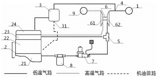
[0058] The anti-emulsification system also includes a solenoid valve 7 and an air filter 8 .

[0059] When in use, the gas flowing out of the vertical air outlet 53 enters the oil pan 21 through the solenoid valve 7 and the air filter 8 in sequence; the opening condition of the solenoid valve 7 is that the speed of the engine 2 is less than or equal to 1000 rpm.


PUM


Abstract

An engine local oil anti-emulsification system comprises an engine, a fresh air inlet, a three-way valve, a supercharger, an oil-gas separator, a solenoid valve and an air filter, wherein the engine successively comprises an oil sump, a cylinder body, a cylinder cover and a cylinder head cover which are connected with each other successively from bottom to top; after flowing out from the supercharger and the three-way valve, gas flowing out from a waste gas outlet and the fresh air inlet is divided into two parts; and one part of the gas enters the cylinder body and is combusted while the other part of the gas successively passes through the solenoid valve, the air filter, the oil sump, the cylinder body, the cylinder cover and the cylinder head cover to dilute and replace waste gas in a crank case of the engine from bottom to top. By the design, the problem of oil emulsification can be solved, gas exchange is full, furthermore, utilization rate of the gas is high, and normal running of the engine is not affected.

Description

technical field [0001] The invention relates to an engine device, in particular to an anti-emulsification system for local engine oil and its application method, which is particularly suitable for replacing and discharging the exhaust gas in the crankcase of the engine with fresh air, preventing the condensation of water vapor in the exhaust gas of the crankcase to emulsify the engine oil . Background technique [0002] At this stage, the development of engines is becoming more and more compact, coupled with the large number of engine parts, the internal structure of the engine is complicated, especially the engine gear train and other components are more complicated, forming a corresponding independent space inside the engine. At the same time, many parts of the engine need to be cooled and lubricated. After the engine stops, the engine oil will remain in the gear room and other places. If the retained oil is not properly disposed of, emulsification problems will occur and ...

Claims


Application Information

Patent Timeline
IPC IPC(8): F01M13/00F01M11/00
CPCF01M11/0004F01M13/0011F01M13/0033F01M2013/0022F01M2013/0038F01M2013/0044F01M2013/0088
Inventor 贾李水叶波李建华潘亮吴娟娟
Owner DONGFENG COMML VEHICLE CO LTD
Why Eureka
Try Eureka