Light synthesis control system and projector
A control system and controller technology, applied in optics, instruments, projection devices, etc., can solve the problems of low red content, the gap between color coordinates and color gamut standards, and the low proportion of red light brightness.
- Summary
- Abstract
- Description
- Claims
- Application Information
AI Technical Summary
Problems solved by technology
Method used
Image
Examples
Embodiment 1
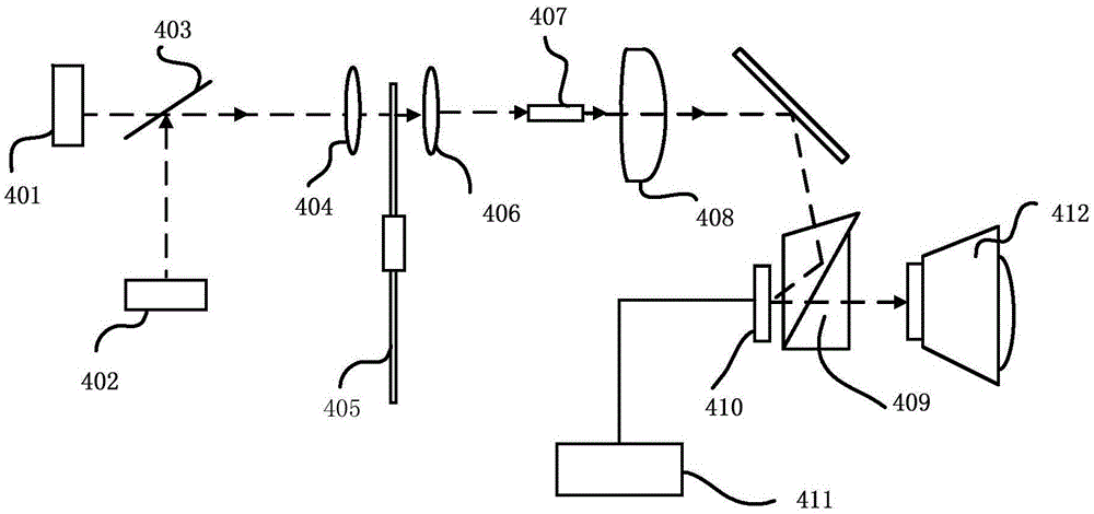
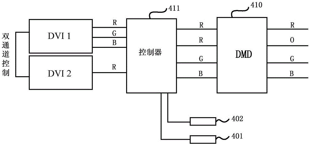
[0024] Please refer to figure 1 , this implementation discloses a light combining control system (hereinafter referred to as the control system), which includes a light source module, a spatial light modulator 410 and a controller 411 . Instructions are given below.
[0025] The light source module is used to emit the primary color light to be compensated and the primary color compensation light, and the primary color compensation light is used to synthesize the first primary color light with the primary color light to be compensated. In some embodiments, the light source module may include a light emitting component and a wavelength converter 405 . The light emitting component may include an excitation light source 401 for emitting excitation light and a compensation light source 402 for emitting compensation light. The excitation light source 401 can be a blue light emitting diode, an ultraviolet light emitting diode or an array thereof, or a blue laser diode, an ultraviol...
Embodiment 2
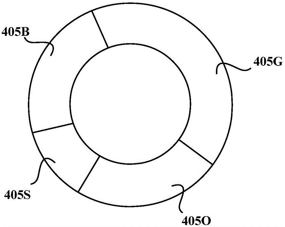
[0034] Please refer to Figure 5 , this embodiment proposes a light-combining control system, which differs from Embodiment 1 in that the wavelength converter 405 in Embodiment 1 is a four-segment type, while the wavelength converter 405 in this embodiment is a six-segment type , including a green phosphor segment 405G, a blue scatterer segment 405B, an orange phosphor segment 405O, and three scatterer segments 405S, wherein the green phosphor segment 405G, the blue scatterer segment 405B and the orange phosphor segment 405O constitute The primary color light is segmented, and the three-scattering body segment 405S constitutes the compensation light segment. In a preferred embodiment, two of the three segments of the green phosphor segment 405G, the blue scatterer segment 405B and the orange phosphor segment 405O are There is a dispersing body segment 405S between the two, therefore, these three dispersing body segments 405S can be understood as a three-segment wavelength conv...
Embodiment 3
[0038] In some other embodiments, the primary color light to be compensated and the primary color compensation light may not be sequentially emitted to achieve light combination, but simultaneously emitted to achieve light combination, which will be described in detail below.
[0039] In this example, if Figure 8 As shown, the control system includes a light source module, a spatial light modulator and a controller 511, which will be described in detail below.
[0040] The light source module may include a light emitting component and a wavelength converter 505 . In a specific embodiment, the light emitting component may include an excitation light source 501 for emitting excitation light and a compensation light source 502 for emitting compensation light. The excitation light source 501 may be a blue light emitting diode, and the compensation light source 502 may be a red laser diode. The wavelength converter 505 is located on the optical path of the excitation light and th...
PUM
 Abstract
Description
Claims
Application Information
 - R&D
- Intellectual Property
- Life Sciences
- Materials
- Tech Scout
- Unparalleled Data Quality
- Higher Quality Content
- 60% Fewer Hallucinations
Browse by: Latest US Patents, China's latest patents, Technical Efficacy Thesaurus, Application Domain, Technology Topic, Popular Technical Reports.
© 2025 PatSnap. All rights reserved.Legal|Privacy policy|Modern Slavery Act Transparency Statement|Sitemap|About US| Contact US: help@patsnap.com


