Experimental device and experimental method for measuring fluid viscosity using microfluidic technology
A microfluidic technology and fluid viscosity technology, applied in the field of microfluidic chips, can solve the problems of low precision, bulky, difficult maintenance, etc., and achieve the effects of high accuracy, low cost, and wide measurement temperature range
- Summary
- Abstract
- Description
- Claims
- Application Information
AI Technical Summary
Problems solved by technology
Method used
Image
Examples
Embodiment 1
[0040] Embodiment 1: Feasibility of deionized water verification experiment
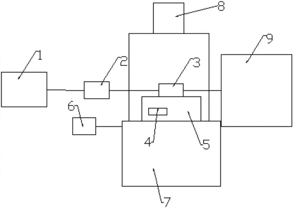
[0041] (1) In order to verify the feasibility of the experiment, at first the test is carried out for deionized water, and the fluorescent particle solution is directly used as the sample for the test, and an appropriate amount of the fluorescent particle solution is injected with the micro-injector 2, and then the micro-injector 2 is set at a constant temperature. Pressure pump 1, after setting the relevant parameters on the constant pressure pump 1 board, the sample can be injected;
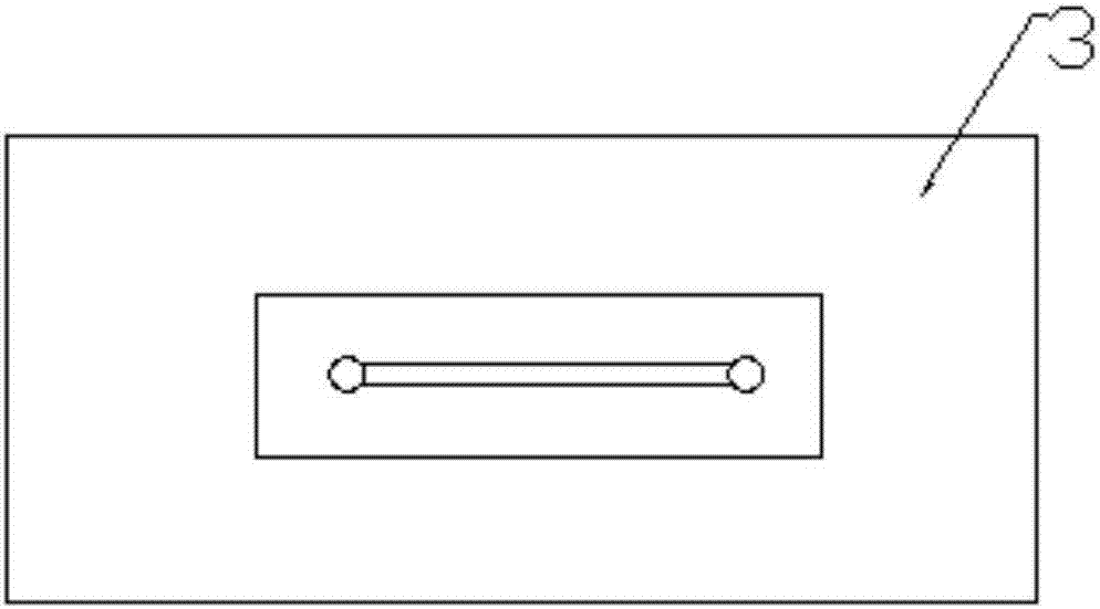
[0042] (2) Turn on the constant pressure pump 1 to inject the sample into the microfluidic chip 3, fill the channel of the microfluidic chip 3 with the sample and flow out a little, then suspend the injection, and then start to adjust the upright fluorescence microscope 7 so that the field of view under the eyepiece is micro In the middle section of the 3 channels of the fluidic chip, and the size is appropriate, conn...
Embodiment 2
[0046] Example 2: Flow Field Observation and Simulation Verification of Oil Phase
[0047] The oil phases used are machine oil and glycerin, respectively. The COMSOL Multiphysics simulation software is selected for verification.
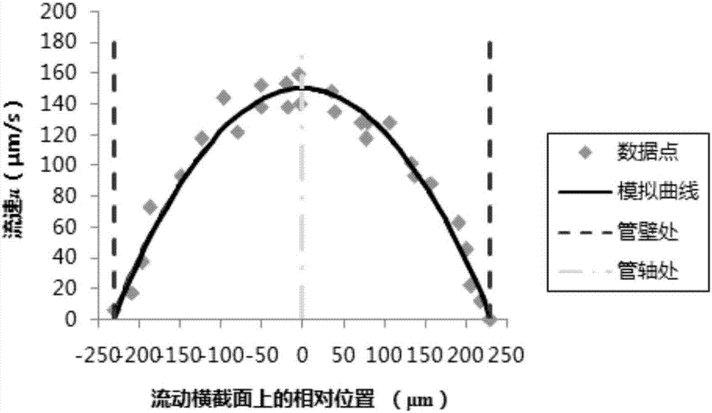
[0048] After the surface of the fluorescent particles is treated with hydrophobicity, an oil phase is added to indicate its flow field distribution. The specific operation steps are the same as the observation of the water phase in Example 1, and the inlet pressure is controlled at 1.5 atmospheres. And after completing a group of observations, adjust the temperature of the temperature control system 4 to 348K, and repeat the measurement steps once the system is stable. The flow field distribution of engine oil and glycerin can be obtained as Figure 4 and Figure 5 .
[0049] Depend on Figure 4 It can be seen that under the condition of constant pressure, the oil flow field can be measured by experimental observation. Through fitting, the dynamic...
Embodiment 3
[0052] Example 3: Effect of temperature on oil phase flow field and viscosity result fitting
[0053] Based on Example 2, the flow field distributions of the two oil products were simulated under more temperature conditions, and 5 of them were selected for illustration. The velocity distribution curve of engine oil at different temperatures is as follows: Figure 6 As shown, the velocity distribution curves of glycerol at different temperatures are as follows Figure 7 shown. It can be seen that the velocity distribution curve of engine oil is obviously different from the peak-type laminar flow curve of glycerol, which is similar to the flat-type laminar flow curve. The flat laminar flow is beneficial for carrying cuttings and stabilizing the borehole wall, which meets the characteristics of engine oil and is also the characteristic required for drilling fluid.
[0054] Further comparison of the flow rate distribution diagrams of engine oil and glycerin shows that the visco...
PUM
| Property | Measurement | Unit |
|---|---|---|
| diameter | aaaaa | aaaaa |
| dynamic viscosity | aaaaa | aaaaa |
| dynamic viscosity | aaaaa | aaaaa |
Abstract
Description
Claims
Application Information
 - R&D
- Intellectual Property
- Life Sciences
- Materials
- Tech Scout
- Unparalleled Data Quality
- Higher Quality Content
- 60% Fewer Hallucinations
Browse by: Latest US Patents, China's latest patents, Technical Efficacy Thesaurus, Application Domain, Technology Topic, Popular Technical Reports.
© 2025 PatSnap. All rights reserved.Legal|Privacy policy|Modern Slavery Act Transparency Statement|Sitemap|About US| Contact US: help@patsnap.com


