Automatically-controlled reciprocating load loading device for axial force-bearing component and using method thereof

A technology of loading device and force-bearing components, applied in the field of steel structure buildings, can solve the problems of component damage, lack of lateral support, and inability to test components, and achieve the effect of facilitating transportation and placement, and avoiding shear stress.

Inactive Publication Date: 2017-02-01
XI'AN UNIVERSITY OF ARCHITECTURE AND TECHNOLOGY
View PDF11 Cites 7 Cited by
  • Summary
  • Abstract
  • Description
  • Claims
  • Application Information

AI Technical Summary

Problems solved by technology

[0005] In the past, the research on the static force and hysteresis performance of axially stressed members was mainly carried out in professional laboratories of universities. Due to the characteristics of the experimental loading device being inconvenient to move and transport, there are certain limitations. Components cannot be tested in some specific environments
At present, there is seldom a professional portable automatic loading device for axially stressed members. At the same time, due to the initial defects such as initial bending and initial eccentricity of the axially stressed members and the lack of corresponding lateral supports, it is easy to use during the loading process. The local failure of the component occurs before the overall failure, which greatly affects the accuracy and results of the experiment

Method used


Image

  • Automatically-controlled reciprocating load loading device for axial force-bearing component and using method thereof
  • Automatically-controlled reciprocating load loading device for axial force-bearing component and using method thereof
  • Automatically-controlled reciprocating load loading device for axial force-bearing component and using method thereof

Examples


Embodiment Construction

[0045] The present invention is described in further detail below in conjunction with accompanying drawing:

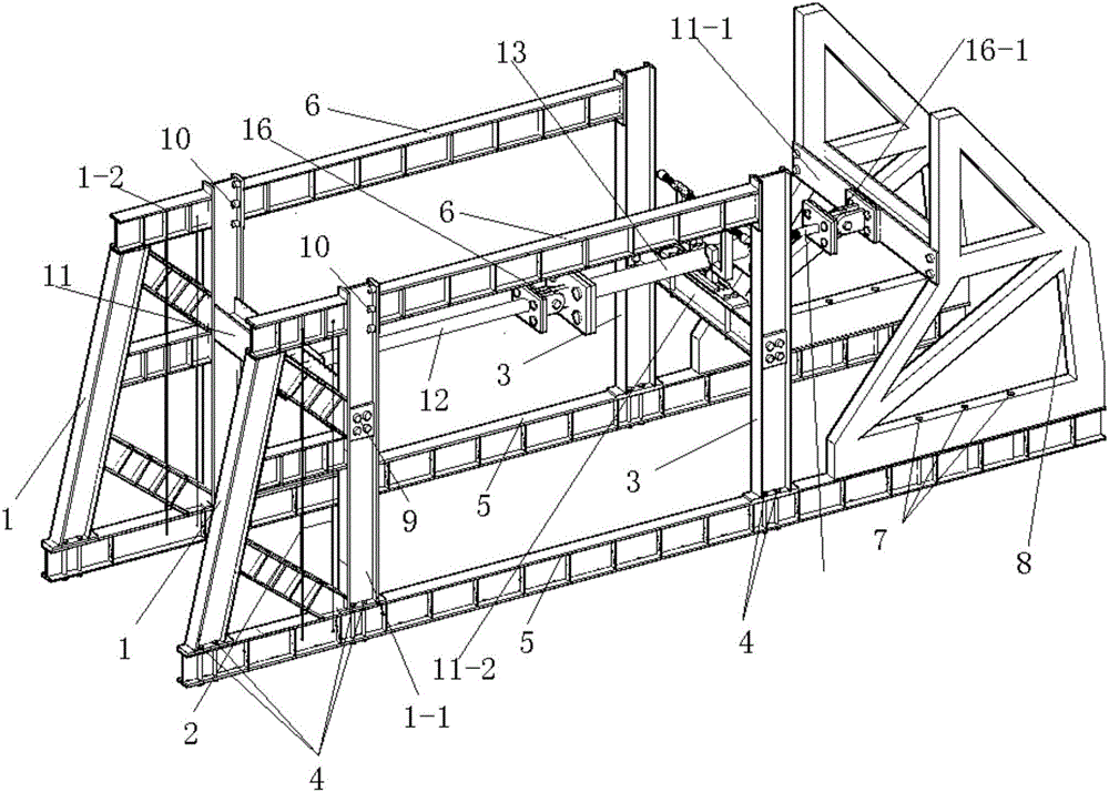
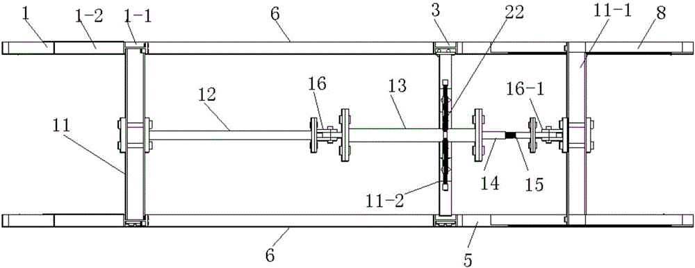
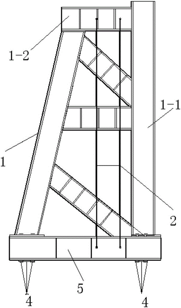
[0046] Such as Figure 1 to Figure 4 As shown, the reciprocating load loading device for automatically controlling the axial center force member of the present invention includes an external frame fixing device. The external frame fixing device is provided with a test piece loading device for loading the test piece 13. The test piece loading device is connected with data collection system;

[0047] The external frame fixing device includes I-shaped steel beam caps 5 arranged side by side. The left and right sides of the I-shaped steel beam caps 5 are respectively connected with a trapezoidal horizontal reaction frame 1 and a triangular reaction frame 8 . The trapezoidal horizontal reaction frame 1 applies the prestressed prestressed steel cable 2, the upper end of the prestressed steel cable 2 is connected with the upper beam 1-2 of the trapezoidal horizontal reaction...


PUM


Abstract

The invention, which belongs to the steel structure building field, particularly relates to an automatically-controlled reciprocating load loading device for an axial force-bearing component and a using method thereof. The automatically-controlled reciprocating load loading device comprises an outer frame fixing device provided with a test piece loading device for loading on a to-be-tested piece; and a data acquisition system is connected to the test piece loading device. A second cross beam and a third cross beam are arranged on the outer frame fixing device. The a test piece loading device consists of a horizontal actuator, a horizontal load sensor and a connecting rod; the horizontal actuator and the horizontal load sensor are connected with the data acquisition system; the left end of the horizontal actuator is fixedly connected with the second cross beam and the right end is connected with the left end of the to-be-tested piece by a first connecting hinge; and the right end of the to-be-tested piece is connected with the horizontal load sensor fixedly. The horizontal load sensor and the connecting rod are connected in a relative rotation mode; and the connecting rod is hinged to the third beam by a second connection hinge. The horizontal actuator, the to-be-tested piece, the horizontal load sensor, and the connecting rod are arranged coaxially and horizontally. The automatically-controlled reciprocating load loading device having a simple structure can be transported and placed conveniently.

Description

[0001] 【Technical field】 [0002] The invention belongs to the field of steel structure buildings, and in particular relates to a reciprocating load loading device for automatically controlling axial force bearing members and a use method thereof. [0003] 【Background technique】 [0004] In the field of steel structures, axially stressed members are widely used in various load-bearing steel structures, such as roof trusses, brackets, towers, net frames, reticulated shells and other types of planar or spatial lattice systems and support systems. middle. The quality of its static and hysteretic performance has a great influence on the seismic performance of the overall structure. Accurate testing of the static and hysteretic performance of axially stressed members is of great importance in reflecting the deformation characteristics, stiffness degradation and energy consumption of the structure. significance. [0005] In the past, the research on the static and hysteretic perfor...

Claims


Application Information

Patent Timeline
Patent Type & Authority Applications(China)
IPC IPC(8): G01M13/00
CPCG01M13/00
Inventor 杨俊芬战宇皓程锦鹏谢坚李宝琪闫西峰
Owner XI'AN UNIVERSITY OF ARCHITECTURE AND TECHNOLOGY
Why Eureka
Try Eureka