
Staggered tooth type thermal insulation building blocks and thermal insulation wall body bricklaying method

A technology for thermal insulation walls and thermal insulation blocks, which is applied to walls, buildings, building materials, etc., to achieve the effect of speeding up construction, simple, convenient and economical construction, and good integrity

Active Publication Date: 2017-02-01
邹城市正通公路工程有限公司
View PDF15 Cites 1 Cited by
  • Summary
  • Abstract
  • Description
  • Claims
  • Application Information

AI Technical Summary

Problems solved by technology

[0005] The invention provides a staggered tooth-shaped thermal insulation block and a wall masonry method. A single thermal insulation block is used without using other thermal insulation layers to avoid thermal bridges in non-thermal insulation parts of blocks and masonry joints. Effect, improve the thermal insulation effect of the external wall, effectively solve the problem of building energy saving, and the masonry process adopts dry operation, the construction is simple, convenient and economical, and can be applied to the requirements of different self-insulation walls

Method used


Image

  • Staggered tooth type thermal insulation building blocks and thermal insulation wall body bricklaying method
  • Staggered tooth type thermal insulation building blocks and thermal insulation wall body bricklaying method
  • Staggered tooth type thermal insulation building blocks and thermal insulation wall body bricklaying method

Examples


Embodiment Construction

[0026] In order to further illustrate the present invention, the present invention will be described in detail below in conjunction with the accompanying drawings and embodiments, but they should not be construed as limiting the protection scope of the present invention.

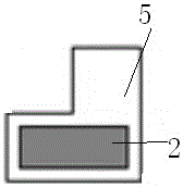
[0027] combine figure 1 and figure 2 , the staggered tooth-shaped thermal insulation block includes a staggered tooth-shaped thermal insulation main block and a staggered tooth-shaped thermal insulation matching block, and the staggered tooth-shaped thermal insulation main block includes a non-interface side horizontal thermal insulation board 1, a protruding large interface horizontal thermal insulation board 2. Recessed interface 3, large protruding interface 4 and small protruding interface 5;

[0028] One side of the staggered tooth-shaped thermal insulation main block is set to be zigzag with unequal height, and the other side is set to be straight, and a large protruding interface 4 is arranged in th...


PUM


Abstract

Staggered tooth type thermal insulation building blocks and a thermal insulation wall body bricklaying method are provided. The staggered tooth type thermal insulation building blocks comprise staggered tooth type thermal insulation main building blocks and staggered tooth type thermal insulation secondary building blocks; a side of each of the staggered tooth type thermal insulation main building blocks is set to be a zigzag shape with different heights, and another side is set to be straight; a large protruding interface is arranged in a center of the zigzag shape side with different heights; both ends of the zigzag shape side with different heights are provided with two small protruding interfaces; a recess interface is disposed between the large protruding interface and the small protruding interface; a transverse thermal insulation plate at a non-interface side is disposed inside the straight side; a protruding large interface transverse thermal insulation plate is disposed inside the large protruding interface of the zigzag shape side with different heights; each of the staggered tooth type thermal insulation secondary building blocks is set to be in the form of L, with one side to be a non-interface end and the other side to be an interface end; a small protruding interface is disposed at the interface end, and the protruding large interface transverse thermal insulation plate is disposed inside the non-interface end; the recess interface and a protruding interface on each of the staggered tooth type thermal insulation main building blocks can enable the staggered tooth type thermal insulation main building blocks to be tightly engaged, so that the integrality of the thermal insulation wall body is excellent.

Description

technical field [0001] The invention belongs to the technical field of wall thermal insulation, and in particular relates to a staggered tooth-shaped thermal insulation block and a wall masonry method, in particular to a staggered tooth-shaped thermal insulation block which can avoid the thermal bridge effect of the non-thermal insulation part of the block and the masonry joint Block and wall masonry methods. Background technique [0002] The production and application of blocks are closely related to resources, energy, ecological environment and living conditions. The development of new wall materials in China, the adjustment of product structure, the improvement of equipment technology level, the improvement of product performance and quality, and the improvement of construction application technology will further promote the development of my country's building materials and building energy conservation, and will contribute to my country's sustainable development. The imp...

Claims


Application Information

Patent Timeline
Patent Type & Authority Applications(China)
IPC IPC(8): E04C1/41E04B2/08E04B2/12
CPCE04B2/08E04B2/12E04B2002/0232E04B2002/0263E04C1/41
Inventor 张延年周玲雪
Owner 邹城市正通公路工程有限公司
Learn More