
Small signal amplifying measurement circuit

A technique for amplifying measurement and voltage amplifying circuits, applied in logic circuits using optoelectronic devices, logic circuits using specific components, etc., can solve problems such as small voltage signals, high output impedance of sensors, and harsh working environments, and achieve suppression of common mode Interference, suppression of temperature drift, strong anti-interference effect

Inactive Publication Date: 2017-01-25
张学一
View PDF0 Cites 4 Cited by
  • Summary
  • Abstract
  • Description
  • Claims
  • Application Information

AI Technical Summary

Problems solved by technology

[0002] In computer measurement systems, it is often necessary to collect some non-electrical signals such as pressure, temperature, acceleration, etc. The measurement of such signals is usually to use sensors to convert these non-electrical signals into voltage or current signals, but due to the sensor output impedance High, the output voltage signal is very small (mV level), and the working environment is harsh, so a measurement circuit with high input impedance, high common mode rejection ratio, high stability, and good linearity is required.

Method used


Image

  • Small signal amplifying measurement circuit
  • Small signal amplifying measurement circuit
  • Small signal amplifying measurement circuit

Examples


Embodiment Construction

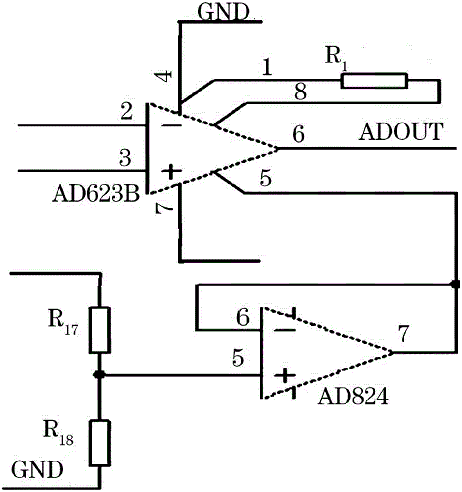
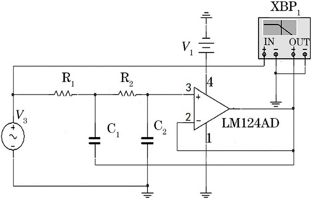
[0016] Such as figure 1 Shown is an overall block diagram of a small signal amplification measurement circuit of the present invention. In the figure, it includes a signal input module, a voltage amplifying circuit, a Serling filter, a voltage follower circuit, an isolation circuit, and a post-stage acquisition system; the key points of its structure are: the output end of the signal input module is connected to the input end of the voltage amplifying circuit , the output of the voltage amplifying circuit is connected to the input of the Serling filter, the output of the Serling filter is connected to the input of the voltage follower circuit, the output of the voltage follower circuit is connected to the input of the isolation circuit, and the output of the isolation circuit The terminal is connected to the input terminal of the post-stage acquisition system.

[0017] Such as figure 2 Shown is a connection diagram of a voltage amplifying circuit of a small signal amplifyin...


PUM


Abstract

The invention discloses a small signal amplifying measurement circuit which can reach 1% accuracy. The circuit has the advantages of common-mode interference inhibiting, temperature excursion inhibiting, high stability and high anti-interference performance. The small signal amplifying measurement circuit comprises a signal input module, a voltage amplifying circuit, a salinger filter, a voltage follow circuit, an isolating circuit and a post collection system. The small signal amplifying measurement circuit is characterized in that an output end of the signal input module is connected with an input end of the voltage amplifying circuit, an output end of the voltage amplifying circuit is connected with an input end of the salinger filter, an output end of the salinger filter is connected with an input end of the voltage follow circuit, an output end of the voltage follow circuit is connected with an input end of the isolating circuit, and an output end of the isolating circuit is connected with an input end of the post collection system.

Description

technical field [0001] The invention belongs to the technical field of high-precision instruments, and in particular relates to a small-signal amplification measurement circuit. Background technique [0002] In computer measurement systems, it is often necessary to collect some non-electrical signals such as pressure, temperature, acceleration, etc. The measurement of such signals is usually to use sensors to convert these non-electrical signals into voltage or current signals, but due to the sensor output impedance High, the output voltage signal is very small (mV level), and the working environment is harsh, so a measurement circuit with high input impedance, high common mode rejection ratio, high stability, and good linearity is required. Contents of the invention [0003] The present invention aims at the above problems, makes up for the deficiencies in the prior art, and provides a small signal amplification measurement circuit; the present invention can achieve 1% ac...

Claims


Application Information

Patent Timeline
Patent Type & Authority Applications(China)
IPC IPC(8): H03K19/14
Inventor 张学一
Owner 张学一
Learn More