
Automatic impedance matching ultrasonic circuit driver and automatic dynamic matching method thereof

An automatic impedance and impedance dynamic technology, applied in electrical components, generators/motors, piezoelectric effect/electrostrictive or magnetostrictive motors, etc., can solve the problem of affecting the performance and stability of ultrasonic systems and reduce system energy rotation. Efficiency, performance improvement bottlenecks, etc., to achieve the effect of improving energy conversion efficiency, fast phase switching, and low heat generation

Inactive Publication Date: 2017-01-25
HARBIN INST OF TECH SHENZHEN GRADUATE SCHOOL
View PDF10 Cites 24 Cited by
  • Summary
  • Abstract
  • Description
  • Claims
  • Application Information

AI Technical Summary

Problems solved by technology

In the field of engineering, the inductance and capacitance used in static matching are determined through human experience, or obtained through continuous trials. The process is time-consuming and labor-intensive, and the obtained inductance and capacitance may not necessarily reach the optimal value.
In addition, when the transducer is in the working process, its load is a dynamic change process. Due to the traditional static matching method, the matched inductance and capacitance are fixed, and online real-time matching cannot be performed on the dynamically changing load, reducing the In addition, it also causes the system to generate a lot of heat, which seriously affects the performance and stability of the ultrasonic system. For the ultrasonic welding, ultrasonic processing, and ultrasonic bonding industries that require high precision, the traditional static matching method becomes The bottleneck of performance improvement

Method used


Image

  • Automatic impedance matching ultrasonic circuit driver and automatic dynamic matching method thereof
  • Automatic impedance matching ultrasonic circuit driver and automatic dynamic matching method thereof
  • Automatic impedance matching ultrasonic circuit driver and automatic dynamic matching method thereof

Examples


Embodiment Construction

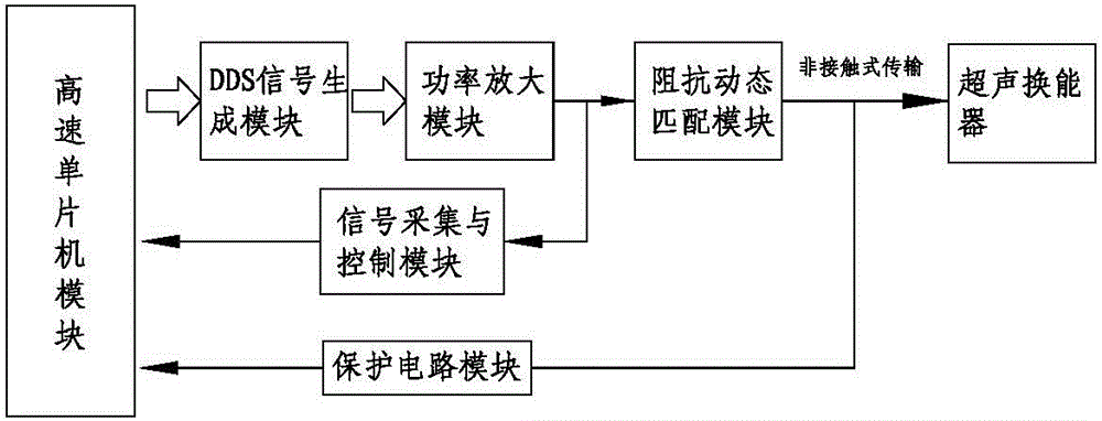
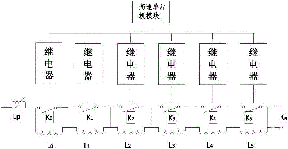
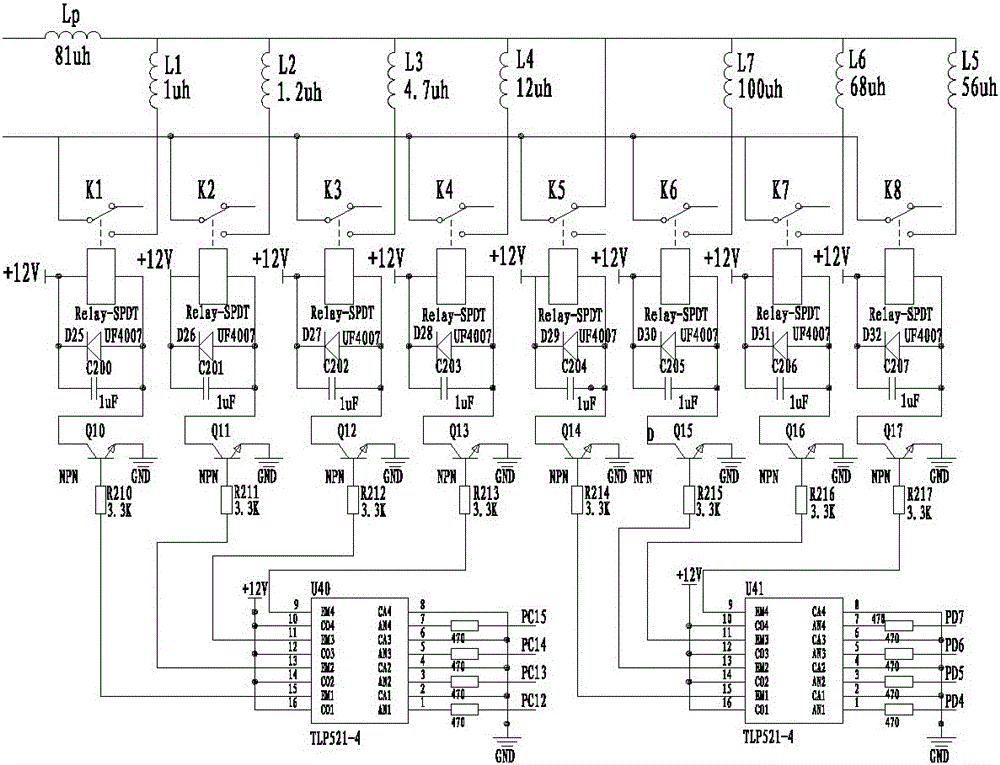
[0024] see Figure 1 to Figure 3 , an ultrasonic circuit driver with automatic impedance matching provided by the present embodiment, which includes a high-speed single-chip microcomputer module connected to each other, a DDS signal generation module, a power amplification module, an impedance dynamic matching module, a signal acquisition and control module and a protection circuit module; wherein The high-speed single-chip microcomputer module is a digital single-chip microcomputer with more than 32 bits, such as ARM and DSP microprocessors. The DDS signal generating module utilizes DDS frequency synthesis technology to generate a sine wave signal in a certain frequency range; the power amplification module adopts a full-bridge circuit composed of IGBT transistors; the impedance dynamic matching is to utilize a series of inductance, according to the circuit The current and phase feedback signals are automatically switched to the required optimal inductance; the signal acquisi...


PUM


Abstract

The invention discloses an automatic impedance matching ultrasonic circuit driver and an automatic dynamic matching method thereof. The automatic impedance matching ultrasonic circuit driver comprises a high-speed single chip module, a DDS signal generation module, a power amplifying module, an impedance dynamic matching module, a signal acquisition and control module and a protection circuit module which are in mutual connection. According to the invention, the design is skillful and reasonable, the dynamic matching module consists of a series of inductance components, the inductance of the dynamic matching module is controlled by a matching algorithm, the resonance of the system on the circuit structure is realized, the energy output of the circuit system is maximum, and reasonable matching between the ultrasonic driver and a transducer is realized. The high-speed single chip module can realize digital control of the whole ultrasonic driver, signal generation is the generation of a sine wave signal by adopting a DDS digital way, the power amplifying module can increase the voltage and current signals into the power required by the transducer, and the signal control module can realize the functions of automatic power tracking and the like.

Description

technical field [0001] The invention relates to the technical field of ultrasonic circuit driving, in particular to an ultrasonic circuit driver with automatic impedance matching. Background technique [0002] With the rapid development of science and technology and major breakthroughs in various fields, ultrasonic applications have crossed most fields, not only occupying a pivotal position in the defense industry, military industry, medicine and life, but also becoming more and more important in the economy. obvious. [0003] The ultrasonic vibration system is mainly composed of ultrasonic driving circuit, matching circuit, transducer and ultrasonic processing tool. Among them, the driving circuit mainly includes signal generation circuit, signal processing and power amplification, etc., which is the energy source of the ultrasonic system; ultrasonic processing tools are generally the execution tools of surgery; The electrical energy is converted into the energy required ...

Claims


Application Information

Patent Timeline
Patent Type & Authority Applications(China)
IPC IPC(8): H02N2/00
CPCH02N2/00
Inventor 隆志力李祚华孙文栋赵爽张建国
Owner HARBIN INST OF TECH SHENZHEN GRADUATE SCHOOL
Learn More