Air cooling structure of magnetic suspension motor

An air-cooled structure and magnetic levitation technology, applied in the direction of electrical components, electromechanical devices, electric components, etc., can solve the problems of long cantilever section of the rotor, no practical function, and the axial position occupied by the cooling fan, so as to improve the linear speed and flow area, increase the supercharging effect and flow rate, and increase the effect of the upper limit of the rotor speed

Inactive Publication Date: 2017-01-25
NANJING CIGU TECH CORP LTD
View PDF6 Cites 1 Cited by
  • Summary
  • Abstract
  • Description
  • Claims
  • Application Information

AI Technical Summary

Problems solved by technology

[0008] 2) Since the cooling fan requires a certain linear speed, only the outer periphery is fan blades, and the wheel is larger and heavier but has no practical function
[0009] 3) The cooling fan needs to occupy a certain axial position, so the cantilever section of the rotor is longer
[0011] 2. Although the external independently driven cooling fan does not affect the upper limit of the rotor speed, it is impossible for the fan motor to use non-lubricated, highly reliable, but expensive magnetic bearings, so it will become a short board that reduces the overall reliability of the magnetic levitation motor

Method used


Image

  • Air cooling structure of magnetic suspension motor
  • Air cooling structure of magnetic suspension motor

Examples


Embodiment Construction

[0027] The present invention will be further described below in conjunction with the accompanying drawings.

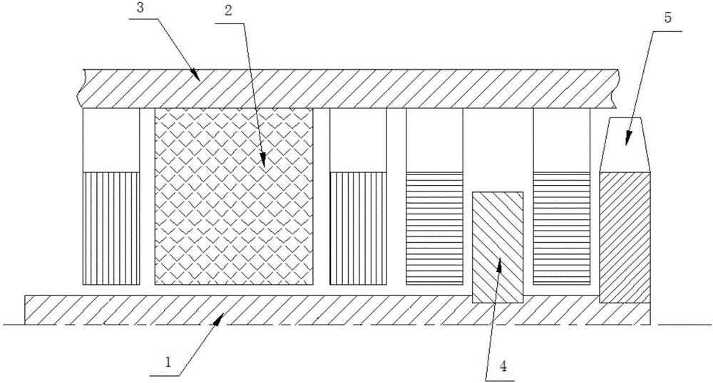
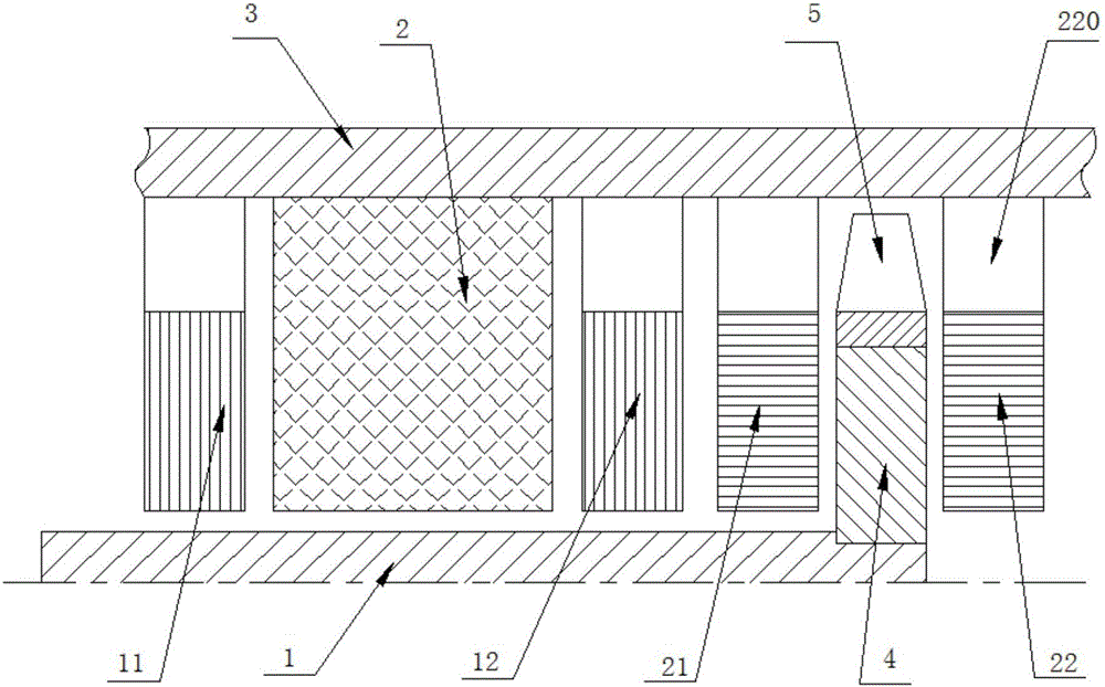
[0028] Such as figure 2 As shown, an air-cooled structure of a magnetic levitation motor in the present invention includes a rotor 1, a stator 2, a housing 3, a first radial magnetic bearing 11, a second radial magnetic bearing 12 and a first thrust magnetic bearing 21, and the first diameter The magnetic bearing 11, the stator 2, the second radial magnetic bearing 12 and the first thrust magnetic bearing 21 are sequentially arranged in the housing 3 from left to right, and the rotor 1 is supported by the first radial magnetic bearing 11, the stator 2, the second thrust magnetic bearing Inside the second radial magnetic bearing 12 and the first thrust magnetic bearing 21 .

[0029] A thrust disc 4, a cooling fan 5 and a second thrust magnetic bearing 22 are also provided in the housing 3, the thrust disc 4 is sleeved on the right end of the rotor 1, and the cooling f...


PUM


Abstract

The invention discloses an air-cooled structure of a magnetic levitation motor, comprising a rotor, a stator, a casing, a first radial magnetic bearing, a second radial magnetic bearing and a first thrust magnetic bearing, the first radial magnetic bearing, a stator, a second The radial magnetic bearing and the first thrust magnetic bearing are sequentially arranged in the casing from left to right, and the rotor is supported in the first radial magnetic bearing, the stator, the second radial magnetic bearing and the first thrust magnetic bearing, and the thrust disc is also included , a cooling fan and a second thrust magnetic bearing, the thrust disk is sleeved on the right end of the rotor, the cooling fan is fixed on the outer peripheral wall of the thrust disk, and the second thrust magnetic bearing is located in the housing and on the right side of the thrust disk. The axial length of the rotor in the thrust disk fan layout is shorter, the cantilever section at the tail is greatly shortened, and the volume of the heavy object at the cantilever end is also reduced by half. Under the condition that other structures of the rotor remain unchanged, the structure of the present invention can effectively improve the bending stiffness of the rotor, thereby Increasing the upper limit of the rotor speed is conducive to giving full play to the advantages of the magnetic suspension bearing.

Description

[0001] Technical field: [0002] The invention relates to an air-cooled structure of a magnetic levitation motor. [0003] Background technique: [0004] The magnetic levitation motor is a high-speed motor with high power density, and the stator and rotor need to have better cooling conditions. At the same time, the high speed also has higher requirements on the natural frequency of the motor rotor, so it is necessary to increase the stiffness of the rotor as much as possible in the structure. [0005] Due to the high power density of the stator and rotor, it is difficult for the air-cooled magnetic levitation motor to be cooled by natural wind, so most of them use special cooling fans for ventilation. The motor cooling fan can be coaxially installed on the motor shaft and driven by the power of the main motor, or it can be externally driven by an independent fan motor. [0006] 1. The structure diagram of the coaxial motor is as follows: figure 1 , as can be seen from the s...

Claims


Application Information

Patent Timeline
Patent Type & Authority Applications(China)
IPC IPC(8): H02K9/06H02K5/16
CPCH02K9/06H02K5/161
Inventor 胡思宁李健吴立华董继勇
Owner NANJING CIGU TECH CORP LTD
Why Eureka
Try Eureka