
Cable release and obstacle crossing construction device

A construction device and obstacle technology, which is applied in the direction of cable installation device, cable installation, cable laying equipment, etc., can solve problems such as pull-off, high cable resistance, and insulation layer damage, so as to save construction cost and improve construction quality , to avoid the effect of wear

Active Publication Date: 2017-01-25
SHANGHE COUNTY POWER SUPPLY CO STATE GRID SHANDONG ELECTRIC POWER CO +1
View PDF5 Cites 5 Cited by
  • Summary
  • Abstract
  • Description
  • Claims
  • Application Information

AI Technical Summary

Problems solved by technology

[0002] When the cable is laid across the bottom of a long-distance obstacle, the resistance to the cable is greater and the traction force required is also greater. When the traction force is greater than the allowable tension of the cable, the cable will undergo plastic deformation, the cross-sectional area will decrease, and the insulation layer will be destroyed. It may even be broken. At the same time, if the cable directly passes through the long-distance casing without protection, the outer sheath of the cable will be severely worn, which will reduce the insulation and waterproof performance of the outer sheath of the cable. As a result, the traditional construction method of directly passing through the casing is no longer Be applicable
[0003] In order to solve the above problems, a construction system for cable underground passage is proposed in the patent application publication number CN 104362572A. The release of the cable is achieved by winch traction, excavator and ground guide rail, and the winch mill is required. Provides a large traction force. At the same time, due to the long distance between the cable drum and the winch mill, the construction process is obviously affected by the crossing distance, which limits the application of the construction system to a certain extent.

Method used


Image

  • Cable release and obstacle crossing construction device
  • Cable release and obstacle crossing construction device

Examples


Embodiment approach

[0017] The subject of protection of the present invention and embodiment are as follows:

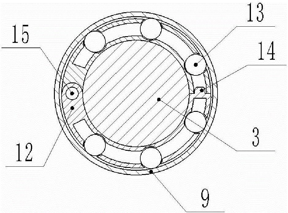
[0018] The cable release provided by the invention and the construction device for crossing obstacles, such as figure 1 As shown, it includes a cable pay-off frame 1, a cable reel 2, a cable 3, a cable release machine 4, a casing 9, a steel wire rope 10, and a winch 11, and the casing 9 includes an inlet end, a horizontal section, and an outlet end. The basic position connection relationship is as follows: the inlet end of the cable pay-off frame 1, the cable release machine 4, and the casing 9 are connected in sequence on one side of the obstacle, and the horizontal section of the casing 9 is located at the bottom of the obstacle and passes through the obstacle. The outlet end of the sleeve pipe 9 and the winch mill 11 are sequentially connected and located on the other side of the obstacle. Wherein, the cable 3 is wound on the cable reel 2, and the cable reel 2 is installed on the cab...


PUM


Abstract

The invention provides a cable release and obstacle crossing construction device, comprising a cable pay-off stand, a cable reel, a cable, a cable release machine, a casing, a steel wire rope, and a winching machine, wherein the cable release device is matched with the winching machine, so that the release of the cable is matched with the laying construction of the cable crossing the bottom of an obstacle, and an auxiliary device is provided in the process that the cable crosses the casing, so that the cable is protected in the process that the cable crosses the casing at the bottom of the obstacle, the traction resistance borne by the cable is reduced, and the wear and tear of a protective covering of the cable are reduced. The construction device provided by the invention is simple to operate in cable laying construction, the cable release and crossing traction are simultaneously realized, the impact of the laying distance of the cable crossing the bottom of the obstacle on the construction can be effectively avoided, the cost is reduced, and the range of application is wide.

Description

technical field [0001] The invention relates to the field of cable construction devices, in particular to a cable release and obstacle crossing construction device. Background technique [0002] When the cable is laid across the bottom of a long-distance obstacle, the resistance to the cable is greater and the traction force required is also greater. When the traction force is greater than the allowable tension of the cable, the cable will undergo plastic deformation, the cross-sectional area will decrease, and the insulation layer will be destroyed. It may even be broken. At the same time, if the cable directly passes through the long-distance casing without protection, the outer sheath of the cable will be severely worn, which will reduce the insulation and waterproof performance of the outer sheath of the cable. As a result, the traditional construction method of directly passing through the casing is no longer Be applicable. [0003] In order to solve the above problems...

Claims


Application Information

Patent Timeline
Patent Type & Authority Applications(China)
IPC IPC(8): H02G1/06H02G1/08
CPCH02G1/06H02G1/085
Inventor 付文波王磊
Owner SHANGHE COUNTY POWER SUPPLY CO STATE GRID SHANDONG ELECTRIC POWER CO
Learn More