


Quick Research
Generate reliable direction feasibility study reports for your R&D in just a few steps.

Technical Q&A
Discover and master advanced knowledge NOW. Basics, ideas, possibilities, all at once.

Find Solutions
As an expert in R&D theories, this can generate solutions to your technical problems instantly.

Evaluate Feasibility
Analyze your overall solution with one click, know your potential R&D risks in advance.

Monitor Landscape
Get weekly tech updates, stay abreast of the latest tech innovations and key insights.
Optical fiber coupler and optical fiber plug
A technology of optical fiber coupler and optical fiber plug, which is applied in the coupling of optical waveguide, light guide, optics, etc., can solve the problems of short transmission distance, low layout density, electrostatic discharge and poor maintainability, and achieve high layout density and improve reliability operation, beneficial to the effect of inspection and maintenance
- Summary
- Abstract
- Description
- Claims
- Application Information
AI Technical Summary
Problems solved by technology
Method used
Image


Examples
Embodiment 1
[0033] The optical fiber coupler includes an external terminal 2 and a board terminal 3; the external terminal 2 is composed of an external terminal base body 21 and N optical fiber plug channels 22 located in the external terminal base body 21, N≥1; the optical fiber plug channel 22 is used to fix the optical fiber plug 1 passing through the optical fiber plug channel 22; the board terminal 3 is composed of a board terminal base body 31 and N light-emitting tube sleeves 32 located in the board terminal base body 31; the light-emitting The tube sleeve 32 is provided with a luminous tube packaging hole 32b for packaging the luminous tube 33; There is a gap between 1 and the luminous tube 33; the optical fiber plug channel 22 corresponds to the luminous tube sleeve 32;
[0034] As a preferred solution, the board terminal base body 31 is made of insulating material, the luminous tube sleeve 32 is made of insulating metal material, and the external terminal base body 21 is made of...
specific Embodiment approach
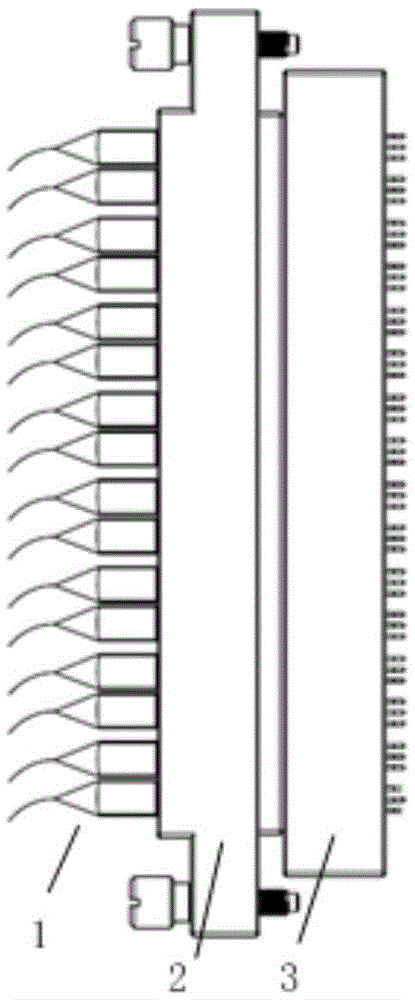
[0037] figure 2 , image 3 , Figure 4 Shown are the front view, side view and cut-away view of a fiber optic coupler with 16 fiber channels. The seat body 21 and 16 optical fiber plug channels 22 are formed, and the board terminal 3 is composed of a board terminal seat body 31 , 16 luminous tube sleeves 32 , 16 luminous tubes 33 and a luminous tube baffle 34 . The 16 optical fiber plugs 1 are all single-core optical fibers, and the outer casing is made of conductive material. Two rows of interleaved parallel connections are adopted, such as figure 2 and image 3 As shown, it is beneficial to further increase the fiber channel arrangement density.
[0038] Figure 5 A sectional view of the external terminal 2 is given, and the external terminal base body 21 is made of conductive material. The optical fiber plug channel 22 includes two parts, namely the optical fiber plug packaging hole 22a and the optical fiber plug fixing hole 22b, and the axes of the two holes are al...
Embodiment 2
[0046] The optical fiber plug is applied to the optical fiber coupler in Embodiment 1, and the outer shell of the optical fiber plug is made of conductive material. The similarities will not be described in detail.
PUM
 Abstract
Description
Claims
Application Information
 - R&D Engineer
- R&D Manager
- IP Professional
- Industry Leading Data Capabilities
- Powerful AI technology
- Patent DNA Extraction
Browse by: Latest US Patents, China's latest patents, Technical Efficacy Thesaurus, Application Domain, Technology Topic, Popular Technical Reports.
© 2024 PatSnap. All rights reserved.Legal|Privacy policy|Modern Slavery Act Transparency Statement|Sitemap|About US| Contact US: help@patsnap.com