Hammer mill

A hammer mill and pulverizer technology, used in solid separation, sieves, grilles, etc., can solve the problems of high pulverization efficiency, short service life, and large relative speed of hammering.

Inactive Publication Date: 2017-01-18
上海春谷机械制造有限公司
View PDF10 Cites 0 Cited by
  • Summary
  • Abstract
  • Description
  • Claims
  • Application Information

AI Technical Summary

Problems solved by technology

[0004] 1. When the material just enters the pulverizer mouth, the direction vector is downward, and the hammer of the pulverizer rotates along the tangential direction of the circle. The relative speed of hammering on the material is high, and the crushing efficiency is high. If they move in the same direction, the relative speed of the pulverizer hammer to the material will be significantly reduced, and if the relative speed is small, the crushing efficiency will be reduced.
[0005] 2. The hammer of the pulverizer rotates in a circ...

Method used


Image

  • Hammer mill
  • Hammer mill
  • Hammer mill

Examples


Embodiment 1

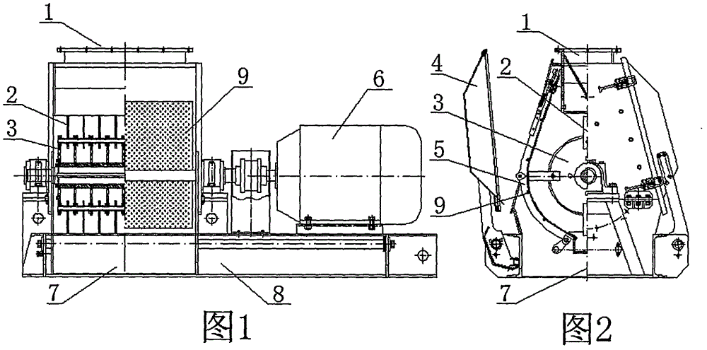
[0019] Embodiment 1: Fig. 1, Fig. 2, a kind of horizontal pulverizer, pulverizer inlet (1), hammer (2), rotor (3), door (4), press screen frame (5), motor (6), pulverizer outlet (7), machine body (8), sieve sheet (9), etc. composition. Hammers are mounted on the rotor. The front end of the hammer is treated with wear-resisting treatment such as tungsten carbide surfacing, and has a beveled edge surface, and the included angle a of the hammer edge angle is 45°. Considering the smooth rotation of the rotor, the Figure 7 When the hammer is used, it can be installed symmetrically and evenly on the front and back. Figure 5 , Image 6 When using two kinds of hammers, install them symmetrically and evenly. No matter which kind of hammer is used, each group of coaxial hammers maintains the same cutting direction, and the other group of hammers can use the opposite direction.

Embodiment 2

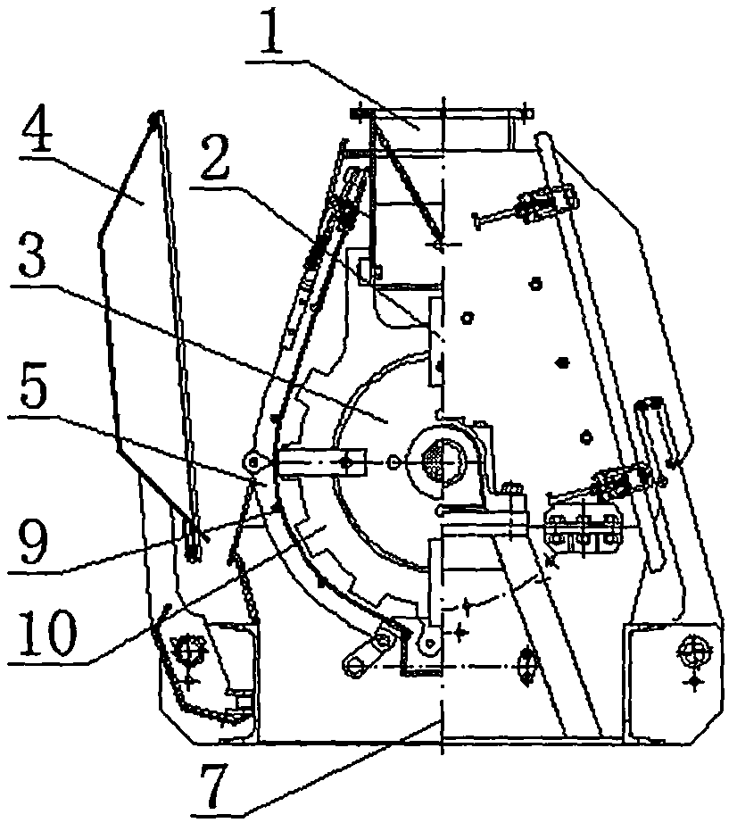
[0020] Example 2: image 3 Among them, a hammer mill with a fixed hammer, the pulverizer feed port (1), hammer (2), rotor (3), door (4), screen press frame (5), motor (6), The pulverizer discharge port (7), body (8), sieve sheet (9), fixed hammer (10) etc. are composed. The installation of the fixed hammer is required to be misaligned with the hammer and keep a certain distance. The installation method of the hammer is the same as that in Example 1.

Embodiment 3

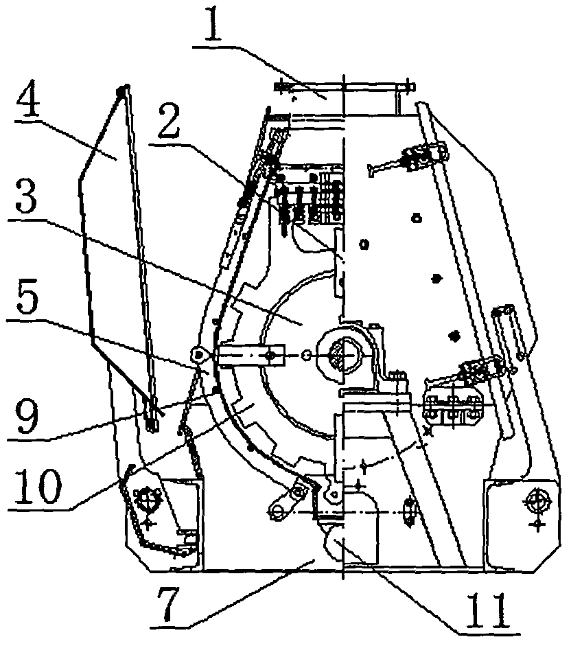
[0021] Example 3: Figure 4 , a hammer mill with vibrating screen, pulverizer inlet (1), hammer (2), rotor (3), door (4), screen press frame (5), motor (6), pulverizer Machine discharge port (7), body (8), sieve sheet (9), fixed hammer (10), vibrating motor (11) and other components. It is characterized in that there is a vibrating motor under the sieve pressing frame (5), the vibrating motor (11) is connected with the sieve pressing frame, and the sieve pressing frame and the sieve (9) can vibrate independently through vibration isolation devices such as springs, and the hammer is installed Method is with embodiment 1.

[0022] Beneficial effect:

[0023] For the pulverizer equipped with sharpened hammers, after the hammers hammer the material, the material no longer rotates with the hammers. In the hammering of another set of hammers, it is still required to maintain a large relative speed difference between the hammers and the materials. . At the same time, in addition ...


PUM


Abstract

The invention provides a hammer mill. The hammer mill is characterized in that a hammer is such designed that two sides of the front end of the hammer are both in a single-sided edged state and the angle a of each edged slope is in a range of 30 to 60 DEG; so after the hammer hammers a material, the material does not rotate around the hammer, the edged slopes allow the material to carry out transverse movement, and a large velocity difference is obtained when a subsequent group of hammer hammers the material. Under the action of the slopes at cutting edges, the surface of a screen mesh located between hammers allows a great number of the material to maintain transverse movement, so crushing efficiency is improved and uniformity of the crushed material is improved; meanwhile, under the action of the slopes at the cutting edges, impact force on the front of the hammer weakens and the service life of the hammer is prolonged.

Description

technical field [0001] The invention relates to a hammer mill, which is usually used in feed, grain, food, chemical, medical and other industries. Background technique [0002] This type of pulverizer usually consists of a pulverizer inlet (1), a hammer (2), a rotor (3), a door (4), a screen press frame) (5), a motor (6), a pulverizer outlet (7) ), a body (8), a sieve (9) and the like. When working, the rotor (3) is driven by the motor (6) to rotate the hammer (2) on the rotor (3), and the material is continuously pulverized by the hammer (2) after entering from the feed port (1). Qualified powder passes through the sieve hole of the sieve (9) and is discharged from the discharge port (7) of the pulverizer. [0003] This type of shredder has the following problems: [0004] 1. When the material just enters the pulverizer mouth, the direction vector is downward, and the hammer of the pulverizer rotates along the tangential direction of the circle. The relative speed of ham...

Claims


Application Information

Patent Timeline
IPC IPC(8): B02C13/13B02C13/28B07B1/28B07B1/42
Inventor 俞信国乐其呈俞正
Owner 上海春谷机械制造有限公司
Why Eureka
Try Eureka