


Quick Research
Generate reliable direction feasibility study reports for your R&D in just a few steps.

Technical Q&A
Discover and master advanced knowledge NOW. Basics, ideas, possibilities, all at once.

Find Solutions
As an expert in R&D theories, this can generate solutions to your technical problems instantly.

Evaluate Feasibility
Analyze your overall solution with one click, know your potential R&D risks in advance.

Monitor Landscape
Get weekly tech updates, stay abreast of the latest tech innovations and key insights.
Axial thrust bearing structure of centrifugal compressor of high-speed motor
A centrifugal compressor, axial thrust bearing technology, applied in machines/engines, components of pumping devices for elastic fluids, mechanical equipment, etc. Compact, increased rotation speed, high efficiency
- Summary
- Abstract
- Description
- Claims
- Application Information
AI Technical Summary
Problems solved by technology
Method used
Image

Examples
Embodiment 1
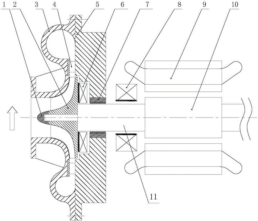
[0030] Embodiment 1, an axial thrust bearing structure of a centrifugal compressor with a high-speed motor, in which an axial thrust bearing 6 is arranged against the back of the impeller 2 . Such an arrangement structure is particularly compact, and there is no need to fix a ring of steel plates on the rotating shaft 11, and then two axial thrust bearings are clamped on both sides of the steel plate ring to shorten the length of the rotating shaft 11.
Embodiment 2
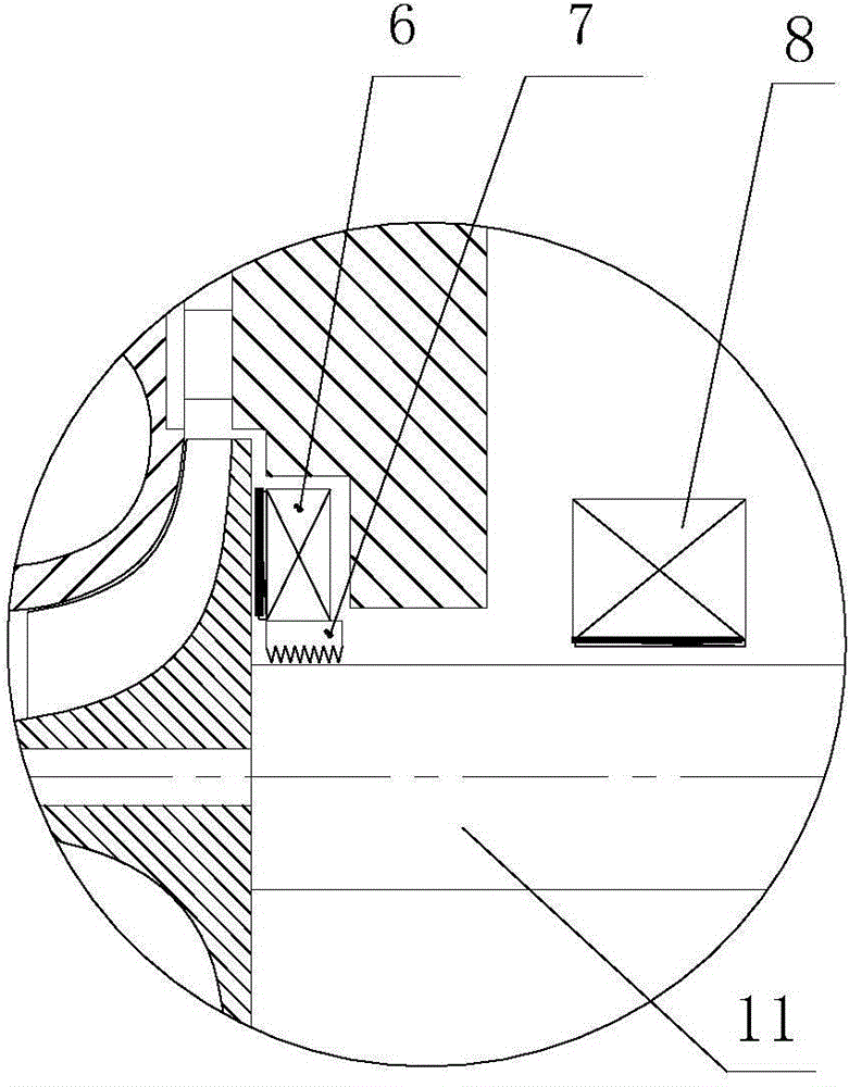
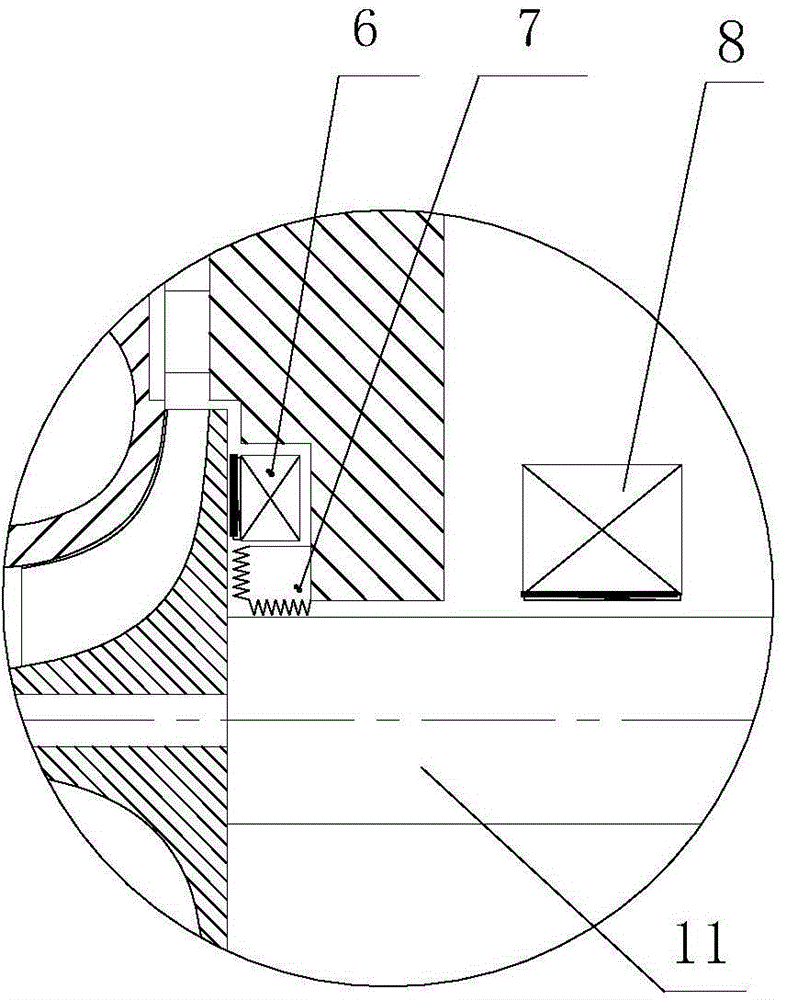
[0031] In Embodiment 2, the axial thrust bearing 6 is arranged against the back of the impeller 2, and the air seal 7 is connected with the axial thrust bearing 6 to form an integral structure. Such configuration is also an obviously compact configuration, fixation and connection structure compared with the prior art, and also serves the purpose of shortening the length of the rotating shaft 11 and the rotor.
Embodiment 3
[0032] Embodiment 3, an axial thrust bearing structure of a centrifugal compressor with a high-speed motor, the compressor impeller 2 is arranged in the volute 3, the volute 3 is fixed on the casing 5 of the compressor, and the rotating shaft 11 of the impeller 2 is fixed Stretch into the central part of the housing 5:
[0033] Axial thrust bearing 6 is arranged against the back of impeller 2, and a section of groove is opened on the corresponding casing 5, and the rear part of the groove is a support section; the inner ring of the support section is fixed with air seal 7, and the sealing surface of air seal 7 is Contact and seal with the rotating shaft 11. The axial thrust bearing 6 of this structure can withstand the axial pressure of the impeller, and the rear support section relies on and supports it. At the same time, using the space in the inner ring of the support section, a fixed air seal 7 is arranged on the inner ring to contact and seal with the rotating shaft 11. ...
PUM
 Abstract
Description
Claims
Application Information
 - R&D Engineer
- R&D Manager
- IP Professional
- Industry Leading Data Capabilities
- Powerful AI technology
- Patent DNA Extraction
Browse by: Latest US Patents, China's latest patents, Technical Efficacy Thesaurus, Application Domain, Technology Topic, Popular Technical Reports.
© 2024 PatSnap. All rights reserved.Legal|Privacy policy|Modern Slavery Act Transparency Statement|Sitemap|About US| Contact US: help@patsnap.com