
Clamping and positioning device for wire electrode of wire-cut electrical discharge machine capable of realizing rapid wire feeding

A cutting machine tool, clamping and positioning technology, applied in the direction of electrode manufacturing, electric processing equipment, metal processing equipment, etc., can solve the problems of electrode wire shaking, guide wheel groove narrow, electrode wire bending and breaking, etc., to improve accuracy and Efficiency, avoiding easy hand injury, and easy tensioning effect

Active Publication Date: 2017-01-11
HUAIAN COLLEGE OF INFORMATION TECH
View PDF9 Cites 3 Cited by
  • Summary
  • Abstract
  • Description
  • Claims
  • Application Information

AI Technical Summary

Problems solved by technology

There are two outstanding problems in this manual wire winding process: on the one hand, the electrode wire is a molybdenum wire of φ0.18mm. Because the molybdenum wire is hard, brittle, and thin, it is easy to fall off when the electrode wire is pulled by hand, and the electrode wire often appears. Bending and breaking, it is easy to cut hands if the force is too large, and the tension of the electrode wire is not enough if the force is small, the electrode wire will vibrate during processing, resulting in short circuit or even broken wire; on the other hand, the groove of the guide wheel is narrow, and the width of the groove is generally not large It is more than 1.5mm, and the diameter of the electrode wire is only 0.18mm. It is difficult to quickly and accurately locate the electrode wire in the narrow groove of the guide wheel in the wire winding, especially when the light is dim, the electrode wire positioning is more difficult.

Method used


Image

  • Clamping and positioning device for wire electrode of wire-cut electrical discharge machine capable of realizing rapid wire feeding
  • Clamping and positioning device for wire electrode of wire-cut electrical discharge machine capable of realizing rapid wire feeding
  • Clamping and positioning device for wire electrode of wire-cut electrical discharge machine capable of realizing rapid wire feeding

Examples


Embodiment Construction

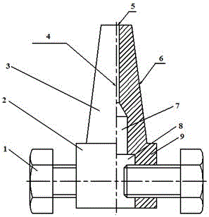
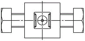
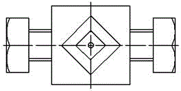
[0023] Combine figure 1 , figure 2 with image 3 As shown, the present invention includes a device body 9. The device body 9 includes a threading part 3 and a clamping part 2 from top to bottom. The top of the threading part 3 is provided with a threading hole 5, and the clamping The bottom of the part 2 is provided with a groove 8, the groove 8 communicates with the threaded hole 5, the two opposite side walls of the clamping part 2 are symmetrically provided with bolts 1, and the ends of the bolts 1 pass through The side wall of the clamping part 2 extends into the groove 8; the threading part 3 is a pyramid structure (in this embodiment, the threading part 3 is a square pyramid structure), and the axis of the threading hole 5 is The center line 4 of the pyramid is collinear; the top section of the pyramid is smaller than the bottom section; the top side of the pyramid is in the range of 3.5~4.5 mm (in this embodiment, the top side of the square pyramid is 4 Mm), the bottom...


PUM

PropertyMeasurementUnit
radiusaaaaaaaaaa
diameteraaaaaaaaaa
diameteraaaaaaaaaa

Abstract

The invention discloses a clamping and positioning device for a wire electrode of a wire-cut electrical discharge machine capable of realizing rapid wire feeding. The device comprises a device body; the device body sequentially comprises a wire penetrating part and a clamping part from top to bottom; a wire penetrating hole is formed in the top of the wire penetrating part; a groove is formed in the bottom of the clamping part and communicates with the wire penetrating hole; bolts are symmetrically arranged on side walls on two opposite sides of the clamping part; and ends of the bolts penetrate through the side walls of the clamping part to extend into the groove. With the structure of the device, the wire electrode can be effectively clamped, and meanwhile, problems that hands are hurt easily and the wire electrode falls off easily when the wire electrode is directly held by hand are solved.

Description

Technical field [0001] The invention relates to the field of wire electrode wire mounting, in particular to an electrode wire clamping and positioning device of an electric spark fast-moving wire cutting machine tool. Background technique [0002] The CNC EDM fast-moving wire-cutting machine tool is uniquely created by the Chinese and is widely used in domestic colleges and universities and small and medium-sized enterprises. Because its wire transportation method is cyclic reciprocating wire transportation, and the wire transportation speed is very fast, up to 8~10m / s, It is almost impossible to automatically install the electrode wire like the slow-moving wire-cutting machine tool. In actual production, the fast-moving wire-cutting machine tool generally uses manual pure manual installation of the electrode wire. That is, after the wire electrode is wound from the wire spool to the wire storage drum of the wire cutting machine, one end of the wire electrode needs to be pulled a...

Claims


Application Information

Patent Timeline
Patent Type & Authority Applications(China)
IPC IPC(8): B23H7/10
CPCB23H7/10
Inventor 王鹏程绳晓婉左庄磊康浩朱威
Owner HUAIAN COLLEGE OF INFORMATION TECH
Learn More