Eureka AIR delivers breakthrough ideas for toughest innovation challenges, trusted by R&D personnel around the world.

Thyristor dimming LED drive power supply and its dimming control method

A technology of LED drive and power supply, which is applied in the field of thyristor dimming LED drive power supply and its dimming control. The effect of light depth and guaranteed power supply

Active Publication Date: 2018-11-13
SHANGHAI BRIGHT POWER SEMICONDUCTOR CO LTD
View PDF7 Cites 0 Cited by
  • Summary
  • Abstract
  • Description
  • Claims
  • Application Information

AI Technical Summary

Problems solved by technology

[0016] When the conduction angle is small, the input voltage Vin is very small, Istart is also very low, and the power supply of the chip is insufficient. When Vin drops to the undervoltage lockout voltage of the chip, the chip stops switching, and the continuous restart of the chip may cause flickering
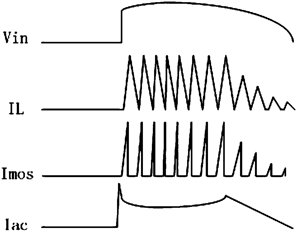
[0017] 2. When the conduction angle is very small (such as Figure 2B As shown), since the input current Iac is the highest when the two shutdown modes are switched, the Iac presents as Figure 2B In the shape shown, in order to ensure sufficient holding current, the output current cannot be reduced, so that the dimming depth cannot be made very deep

Method used


Image

  • Thyristor dimming LED drive power supply and its dimming control method
  • Thyristor dimming LED drive power supply and its dimming control method
  • Thyristor dimming LED drive power supply and its dimming control method

Examples


Embodiment Construction

[0032] The thyristor dimming LED drive power supply and its dimming control method provided by the present invention will be described in detail below in conjunction with the accompanying drawings.

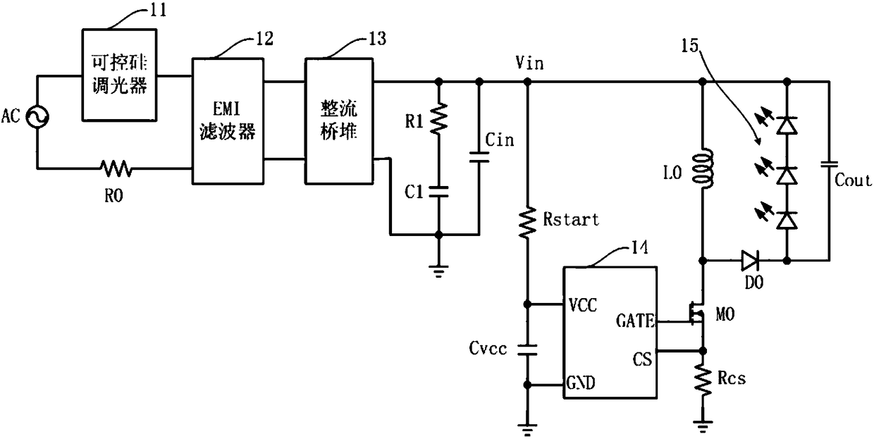
[0033] refer to image 3, a schematic diagram of the structure of the thyristor dimming LED driving power supply described in the present invention. The thyristor dimming LED drive power supply at least includes a dimming control circuit, a driver chip 34 and an LED lamp string 35; wherein the dimming control circuit includes a thyristor dimmer 31, an EMI filter 32, and a rectifier bridge stack 33 , energy storage filter capacitor Cin, damping resistor R0 for attenuating LC oscillation when the thyristor is turned on, and a passive leakage circuit composed of resistor R1 and capacitor C1; one end of the AC power supply AC is electrically connected to the thyristor dimmer 31, the other end is electrically connected to the damping resistor R0; the bypass capacitor Cvcc of the chip ...


PUM


Abstract

The invention discloses a thyristor dimming LED driving power supply and a dimming control method thereof which can improve the dimming depth of thyristor; the driving power comprises a dimming control circuit, a driving chip and an LED lamp string, and the dimming control circuit comprises Input the average voltage sampling module, the input end of the input average voltage sampling module is electrically connected to the input voltage end of the drive power supply, and the output end is electrically connected to the VLN pin of the drive chip; the input average voltage sampling module is used to sample the input average voltage of the drive power supply And send it to the driver chip to adjust the input current waveform of the driver power supply, thereby changing the dimming depth. By sampling the average input voltage to adjust the inductor current at small conduction angles, the dimming depth of the thyristor dimmable LED lamps is improved, and the output current is reduced without reducing the maintenance current; by changing the driver chip The power supply method avoids the possible flicker caused by the continuous restart of the chip.

Description

technical field [0001] The invention relates to the technical field of integrated circuit driving, in particular to a thyristor dimming LED drive power supply and a dimming control method thereof, which can improve the depth of dimming of thyristors, and are applied in the driving industry. Background technique [0002] Compared with traditional light sources, in addition to the advantages of green, energy saving, and environmental protection, LED lighting is also an important advantage of dimming. Common dimming methods include analog dimming, PWM dimming, wall switch dimming and thyristor dimming. Among them, thyristor dimming is the most widely used, especially in North America and Western European countries, almost more than 90% of lamps use thyristor dimming. Dimming depth is an important indicator of thyristor dimming lamps, which represents the minimum LED brightness without flicker when the conduction phase is small. The deeper the dimming depth, the better the end...

Claims


Application Information

Patent Timeline
Patent Type & Authority Patents(China)
IPC IPC(8): H05B33/08H05B44/00
CPCH05B45/10
Inventor 郑儒富闾建晶
Owner SHANGHAI BRIGHT POWER SEMICONDUCTOR CO LTD
Why Eureka
Eureka Blog
Learn More