
Symbol synchronization method based on continuous phase modulation signal phase change features

A phase modulation signal and symbol synchronization technology, which is applied in the field of telecommunications, can solve the problems of large hardware resources, complex consumption of symbol synchronization algorithms, and less calculation amount, and achieve the effect of simple operation, less hardware resource occupation, and low cost

Active Publication Date: 2017-01-04
NO 722 RES INST OF CHINA SHIPBUILDING IND
View PDF4 Cites 8 Cited by
  • Summary
  • Abstract
  • Description
  • Claims
  • Application Information

AI Technical Summary

Problems solved by technology

[0003] Aiming at the above defects or improvement needs of the prior art, the present invention provides a symbol synchronization method suitable for continuous phase modulation signal communication systems, so as to achieve symbol synchronization with only a small amount of calculation, and solve the problem of existing digital The symbol synchronization algorithm in the communication system is too complex and consumes more hardware resources, and at the same time overcome the influence of Doppler frequency offset on the symbol synchronization of the received signal

Method used


Image

  • Symbol synchronization method based on continuous phase modulation signal phase change features
  • Symbol synchronization method based on continuous phase modulation signal phase change features
  • Symbol synchronization method based on continuous phase modulation signal phase change features

Examples


Embodiment Construction

[0020] In order to make the object, technical solution and advantages of the present invention clearer, the present invention will be further described in detail below in conjunction with the accompanying drawings and embodiments. It should be understood that the specific embodiments described here are only used to explain the present invention, not to limit the present invention. In addition, the technical features involved in the various embodiments of the present invention described below can be combined with each other as long as they do not constitute a conflict with each other.

[0021] This embodiment is realized based on FPGA, but this embodiment should not be construed as a limitation to the present invention.

[0022] 1. System

[0023] 1. Overall

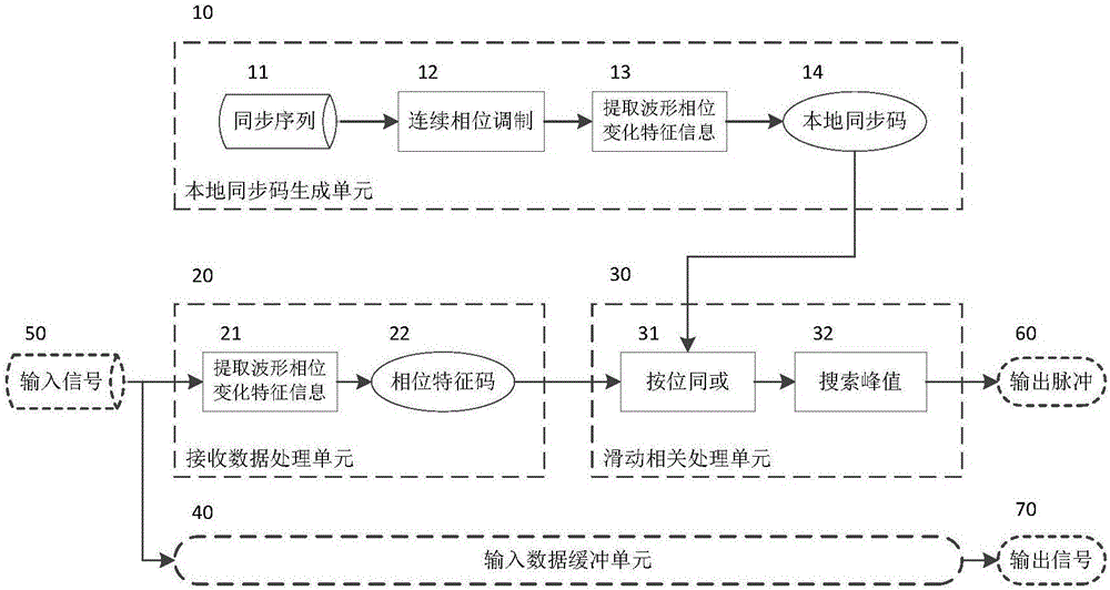
[0024] Such as figure 1 , the system includes a local synchronization code generation unit (10), a received data processing unit (20), a sliding correlation processing unit (30) and an input data buffer unit (40);

[...


PUM


Abstract

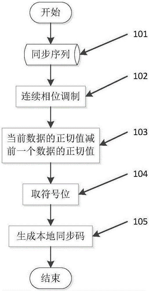
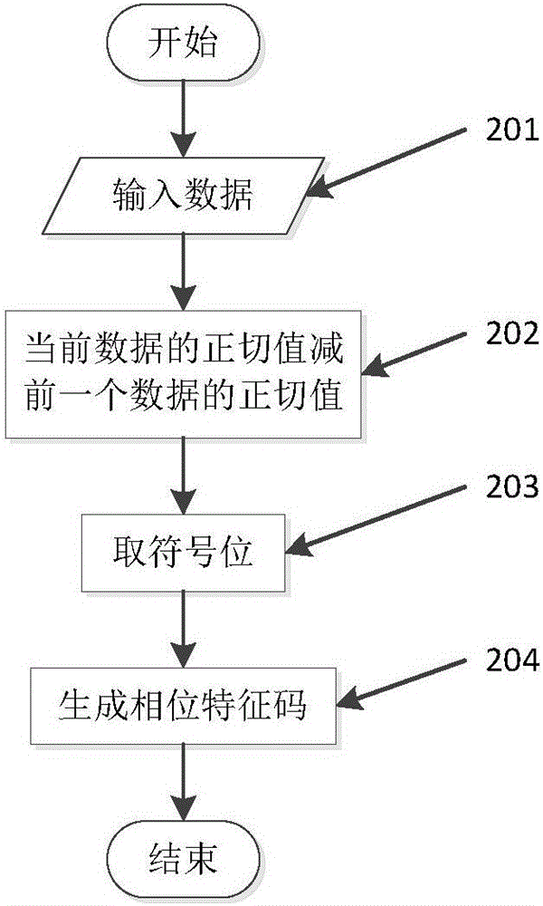
The invention discloses a symbol synchronization method based on continuous phase modulation signal phase change features. The method mainly comprises steps: phase change features of synchronization preamble signals are extracted; correlation operation with local synchronization codes is carried out; the time and the position of a peak during the correlation operation are found out, and symbol synchronization is completed. In view of the problem that the symbol synchronization algorithm in the existing digital communication system is over complicated and hardware resources are much consumed, the starting time and the stopping time for receiving signal symbols can be accurately determined, the operation amount is small, the operation burden of the system is lessened, and the method is particularly suitable for a communication system with hardware resource shortage. In addition, the method can be applied to a situation with Doppler frequency shift, and influences on received signal symbol synchronization by the Doppler frequency shift can be effectively overcome. In a condition with a low signal-to-noise ratio, synchronization can still be reliably realized.

Description

technical field [0001] The invention relates to the technical field of electrical communication, in particular to a method for synchronizing symbols by using phase change characteristics of signals in a communication system of continuous phase modulation signals. Background technique [0002] In digital communication, the purpose of symbol synchronization is to determine the correct start and end moments of each symbol symbol at the receiving end. At present, the methods for realizing symbol synchronization by adding a leading signal mainly include using local matching waveform correlation operations, or using FFT to match in the frequency domain, but these operations are usually more complicated and consume more hardware resources. Contents of the invention [0003] Aiming at the above defects or improvement needs of the prior art, the present invention provides a symbol synchronization method suitable for continuous phase modulation signal communication systems, so as to...

Claims


Application Information

Patent Timeline
IPC IPC(8): H04J3/06H04L27/26
CPCH04J3/0605H04L27/2675
Inventor 李朝阳盛晨辉付兴许振王孜
Owner NO 722 RES INST OF CHINA SHIPBUILDING IND
Learn More