


Quick Research
Generate reliable direction feasibility study reports for your R&D in just a few steps.

Technical Q&A
Discover and master advanced knowledge NOW. Basics, ideas, possibilities, all at once.

Find Solutions
As an expert in R&D theories, this can generate solutions to your technical problems instantly.

Evaluate Feasibility
Analyze your overall solution with one click, know your potential R&D risks in advance.

Monitor Landscape
Get weekly tech updates, stay abreast of the latest tech innovations and key insights.
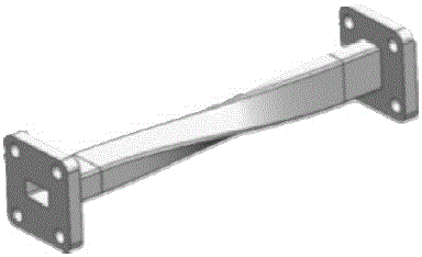
Novel waveguide polarization mode transition diaphragm structure applied in terahertz band
A mode conversion and terahertz technology, applied in waveguide devices, electrical components, connecting devices, etc., can solve the problems of waveguide inner cavity dimensional accuracy and position tolerance, complex processing technology, expensive processing cost, etc., to meet engineering needs, The effect of simple processing technology and low processing cost
- Summary
- Abstract
- Description
- Claims
- Application Information
AI Technical Summary
Problems solved by technology
Method used
Image

Examples
Embodiment Construction
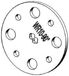
[0025] Such as figure 2 As shown, a new type of waveguide polarization mode conversion diaphragm structure applied in the terahertz frequency band, the entire diaphragm is in the form of a disc structure, and eight symmetrical round holes are arranged on the disc with the center of the circle as the center, including four large round holes and Four small round holes, large round holes and small round holes are arranged at intervals.
[0026] A coupling cavity is provided at the center of the waveguide polarization mode conversion diaphragm structure, and the shape of the coupling cavity is two intersecting rectangles, and the corners of the rectangles are all rounded.
[0027] The coupling cavity may be a shape in which two identical rectangles intersect, or a shape in which two identical squares intersect.
[0028] Taking the standard waveguide WR10 as an example, the thickness of the 90° polarization conversion diaphragm is only 1.14mm, which is very beneficial for switchi...
PUM
 Abstract
Description
Claims
Application Information
 - R&D Engineer
- R&D Manager
- IP Professional
- Industry Leading Data Capabilities
- Powerful AI technology
- Patent DNA Extraction
Browse by: Latest US Patents, China's latest patents, Technical Efficacy Thesaurus, Application Domain, Technology Topic, Popular Technical Reports.
© 2024 PatSnap. All rights reserved.Legal|Privacy policy|Modern Slavery Act Transparency Statement|Sitemap|About US| Contact US: help@patsnap.com