Metal material industrial CT image quality rapid correction method
A CT image and correction method technology, applied in image data processing, 2D image generation, instruments, etc., can solve problems such as complex calculation, long correction time, and difficulty in obtaining original CT image data
- Summary
- Abstract
- Description
- Claims
- Application Information
AI Technical Summary
Problems solved by technology
Method used
Image
Examples
Embodiment Construction
[0046] The present invention will be further described in detail below in conjunction with the accompanying drawings and embodiments.
[0047] like Figure 1-7 Shown, method of the present invention comprises the following steps:
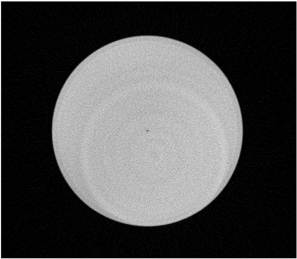
[0048] 1. Read in a CT image with noise and ring artifacts, set its image size as N×N (unit: pixel), that is, N is the number of pixels in each row, for example, 4096×4096 pixels, that is, N=4096 , the gray value of any pixel on the image can be expressed as I(x, y), where (x, y) are the abscissa and ordinate of the point, 0≤x, y≤N. like figure 1 As shown in the figure, the center of the figure is a pore-like defect, and there are some ring artifacts around it.
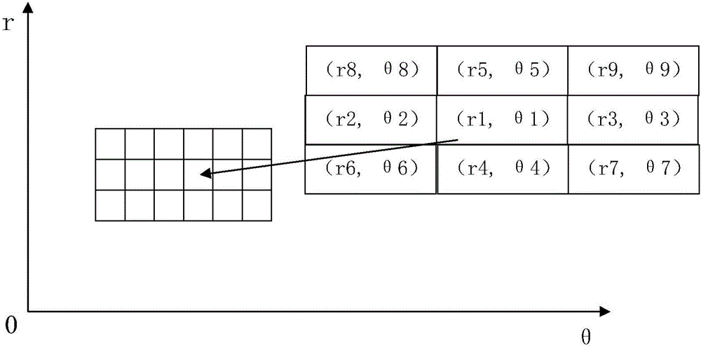
[0049] 2. Create a polar coordinate image with a horizontal axis θ range (0,2π), with an interval of When N is set to 4096, the interval is 0.03. The smaller the interval, the less image information loss, but the longer the program operation time, the interval calculated by this formul...
PUM
 Abstract
Description
Claims
Application Information
 - R&D
- Intellectual Property
- Life Sciences
- Materials
- Tech Scout
- Unparalleled Data Quality
- Higher Quality Content
- 60% Fewer Hallucinations
Browse by: Latest US Patents, China's latest patents, Technical Efficacy Thesaurus, Application Domain, Technology Topic, Popular Technical Reports.
© 2025 PatSnap. All rights reserved.Legal|Privacy policy|Modern Slavery Act Transparency Statement|Sitemap|About US| Contact US: help@patsnap.com


